Introduction:
A rectifier is a circuit that converts the alternating current source into the direct current source. Rectifiers are usually built using diodes that allow only unidirectional current to pass through. The rectifiers are used in devices that require converting electrical energy from one form to another. It can be classified into two main types, single-phase and three-phase, or it can be classified as half-wave, full-wave, and bridge rectifier.
A full-wave rectifier can be built in two configurations, one is the bridge rectifier configuration and the other is a center-tapped transformer with two diodes. A full-wave bridge rectifier is a type of single-phase rectifier circuit in which four diodes are arranged in a bridge configuration and provide a rectified DC output. The four diodes in series rectify the incoming AC signal and two diodes conduct for each half cycle.
Hardware Components
Full-Wave Bridge Rectifier Circuit
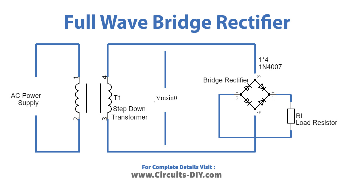
Working Principle:
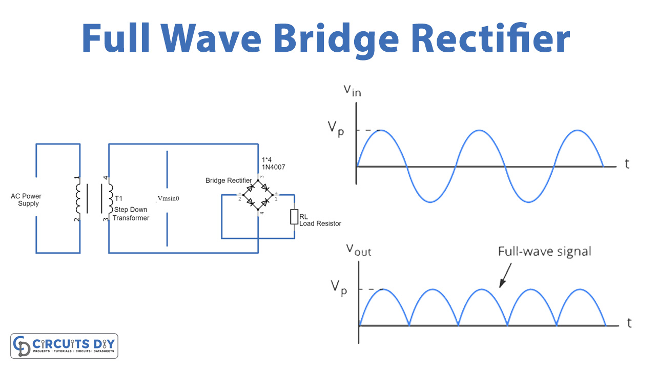
The full-wave bridge rectifier is divided into two steps before applying to the load. The first step is to step down the incoming AC power signal to reduce the voltage to a certain level. The transformer is used to step down the voltage level. The next step is the bridge rectifier that uses four diodes in series, during the positive half cycle the two diodes D1 and D3 conduct, and during the negative half cycle diodes, D2 and D4 conduct, and a converted direct current power output signal are provided to the load.

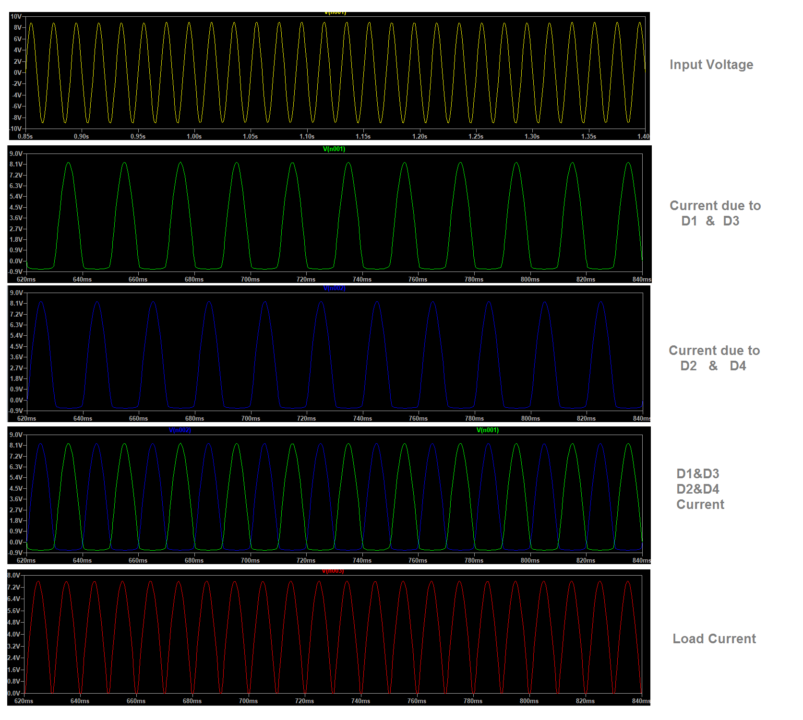
Input & Output Waveforms:
Bridge Rectifier Application Prototypes:
Bridge rectifier circuits can be built using other components. Following are the prototypes of the bridge rectifiers.
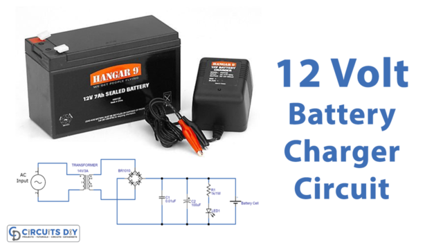
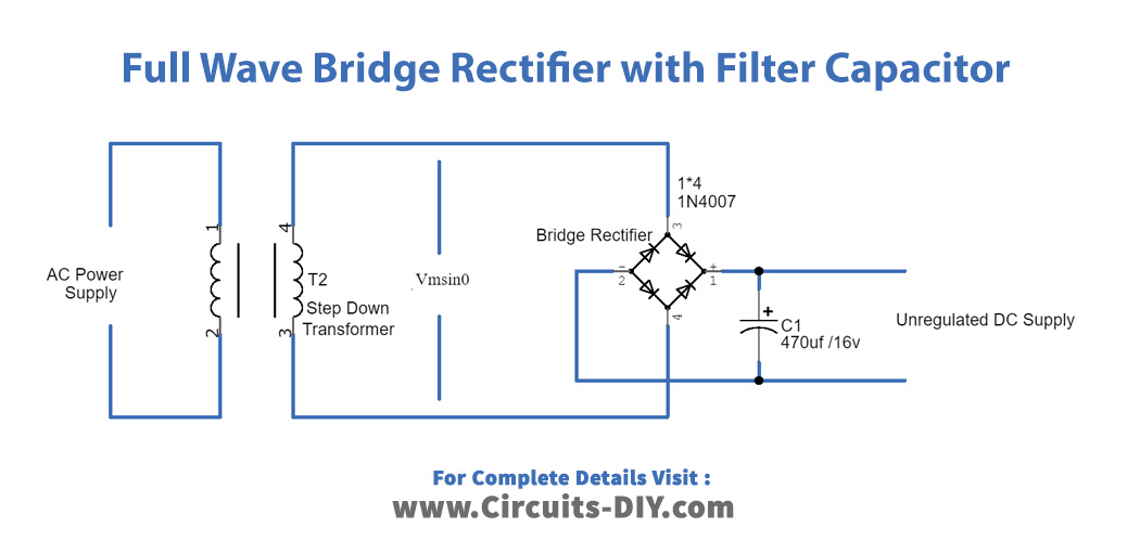
Bridge rectifier with the capacitor filter:
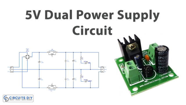
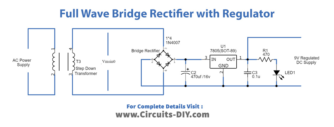
Bridge rectifier circuit with the regulator circuit:
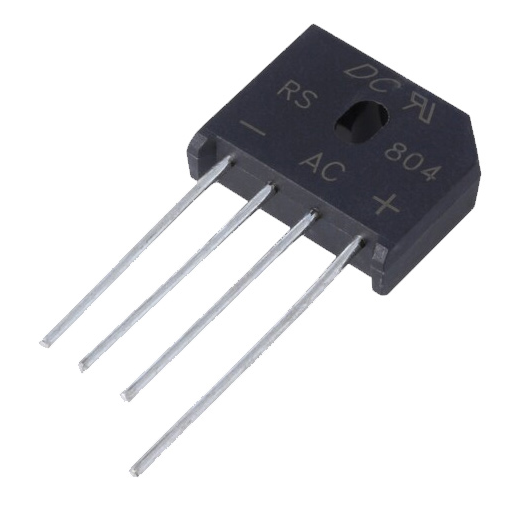
Bridge rectifier IC:
Applications:
The various applications of bridge rectifiers include:
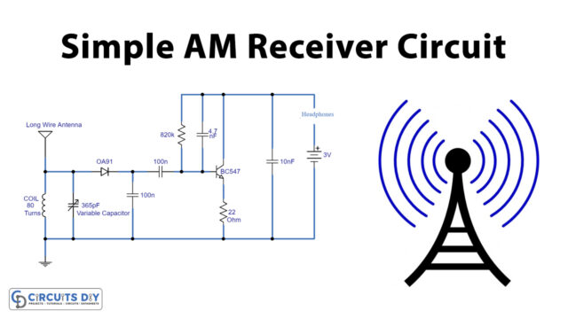
- The amplitude of the radio wave signal is detected using a full-wave bridge rectifier.
- These rectifiers are also used to supply DC voltage in electric welding.
- They are needed to power up the devices like motors or LEDs that need a DC power supply to operate.