
Introduction
In electronic devices and circuits, we consider the power supply one of the important and basic circuits. And, that’s why we have seen that many students start their learning about electronic circuitry through the understanding of power supply circuits. Fundamentally, the power supply converts the AC power into DC power. Therefore, the power supply includes the rectifier circuit in its circuit So, to understand them and to learn the whole circuit, In this tutorial, we are going to “5V Dual power Supply circuit with PCB”. It gives the positive and negative DC supply at the output side.
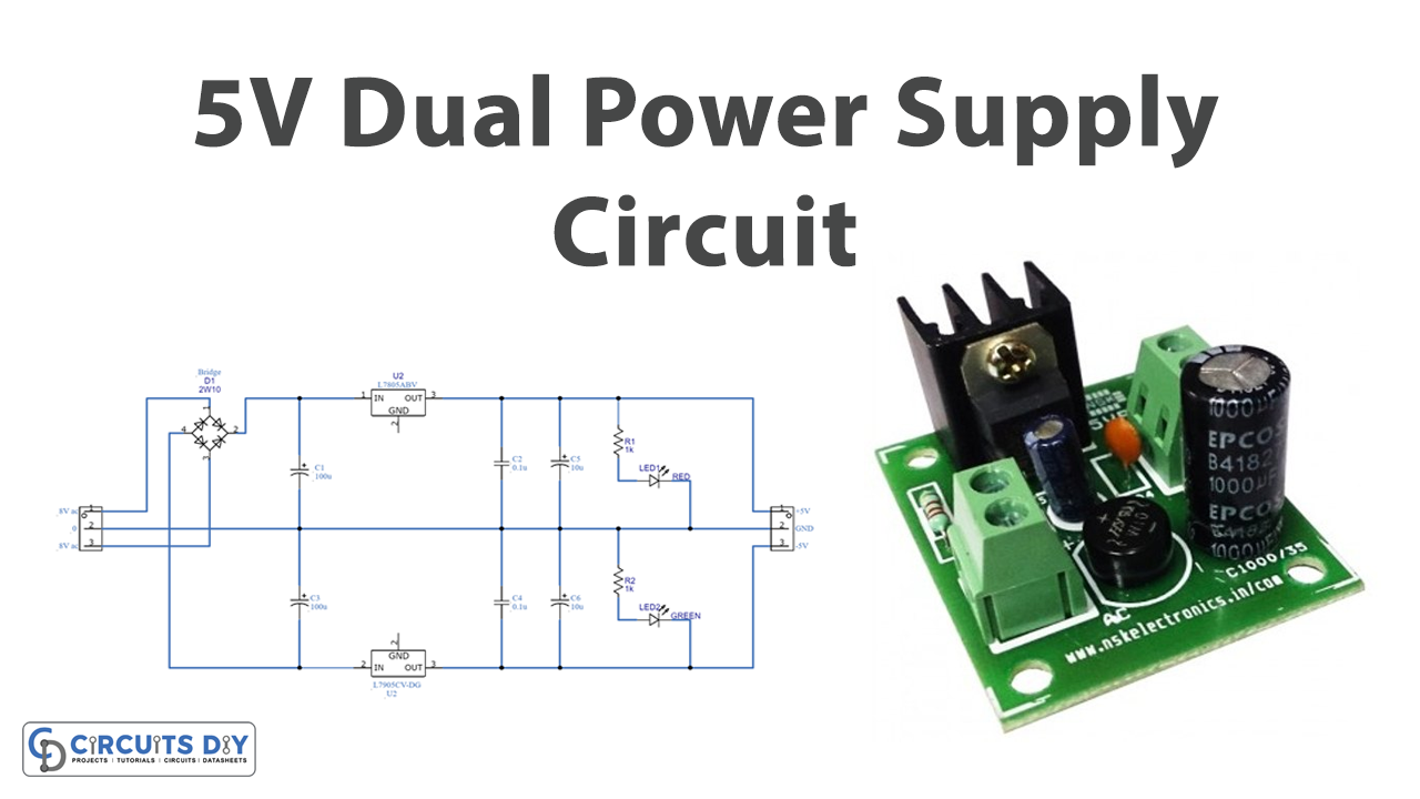
We are making this circuit on the Printed circuit board as it makes the circuit more secure. Thus, you can use any type of PCB-making software for this purpose. Also, make sure to use the better quality PCB to make an effective circuit.
Hardware Required
| S.no | Component | Value | Qty |
|---|---|---|---|
| 1. | IC | L7805 | 1 |
| 2. | IC | L7905 | 1 |
| 3. | Diode | 2W10 | 4 |
| 4. | LED | – | 2 |
| 5. | Capacitor | 0.1uF, 10uF, 100uF | 2, 2, 2 |
| 6. | Resistor | 1KΩ | 2 |
| 7. | 3-Pin Connector | – | 2 |
Circuit Diagram
Working Explanation
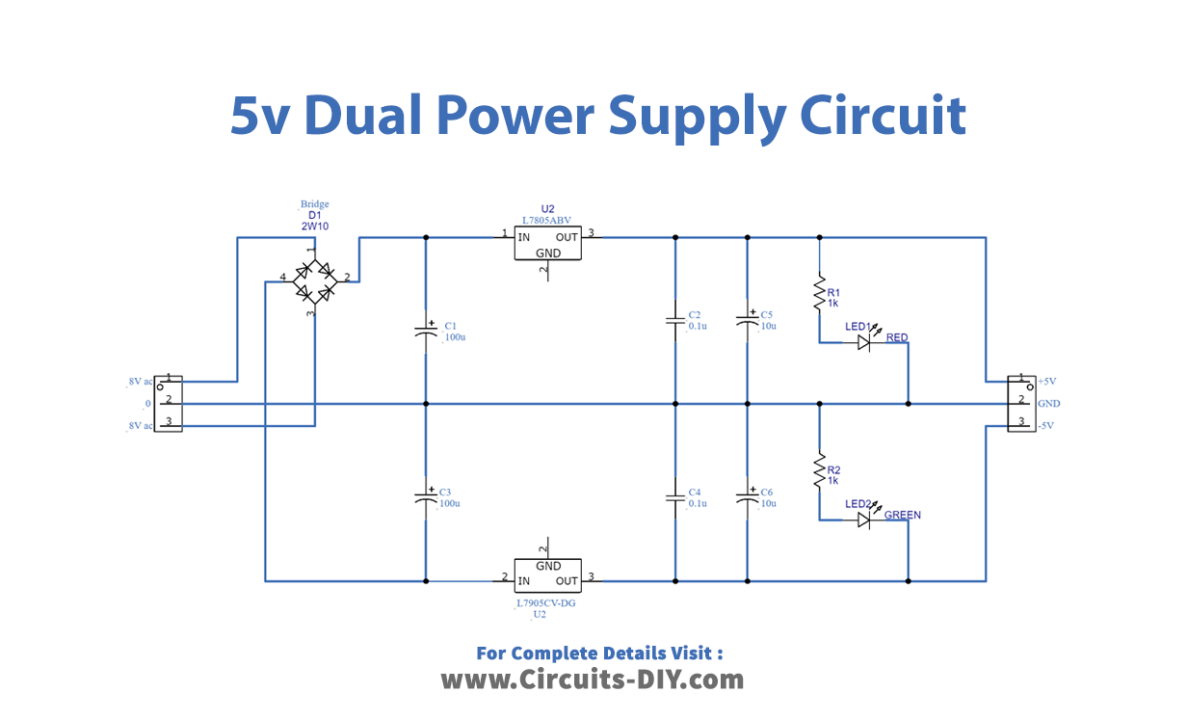
To make a 5V Dual power Supply circuit firstly, we give the 8V-0-8V, coming from the transformer to the full-bridge rectifier circuit, that we have made with the help of diodes. The rectifier converts the AC into DC but it has the DC ripples in it. These DC ripples are filtered by the capacitors C1 and C3 attached to the circuit. Now, this voltage is provided to two different regulators ICs. IC L7805 gives the positive DC voltage, while IC L 7905 provides the negative DC voltage. The voltages get filtered by the capacitors wired in this circuit and we get the dual supply at the output load.
Application and Uses
It is used in many electronic devices and circuits.
Related posts:
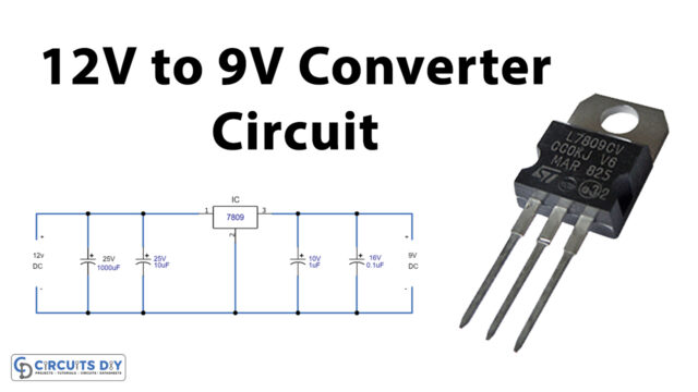 12V to 9V Converter Circuit Using LM7809 Regulator IC
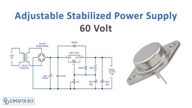 Adjustable Stabilized Power Supply 60v Using LM317HVK
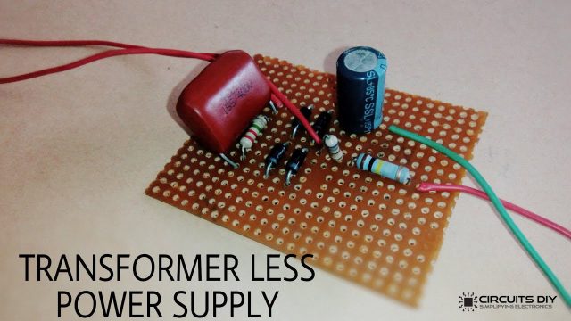 Transformerless Power Supply Circuit - DIY Project
 AMS1117-3.3V Power Supply Module Voltage Regulator
 Reasons to Choose JLCPCB as your SMT PCB Manufacturer
 High Speed Printed Circuit Board Design Tips


