Designing efficient power supplies is a major concern of today’s electronics, as one of the main issues in modern-day electronics is to efficiently generate low-voltage DC from an AC source such as a wall outlet to power any circuit. One solution that might occur in one’s mind is a transformer-based power supply, which steps down the AC source, in order to be rectified to a usable DC Supply level. But even though transformer-based supplies are quite useful, they often turn out to be quite expensive and require a lot of space for proper accommodation. So, in this project, we are going to design a simple & compact Capacitive Transformerless DC Power Supply Circuit.
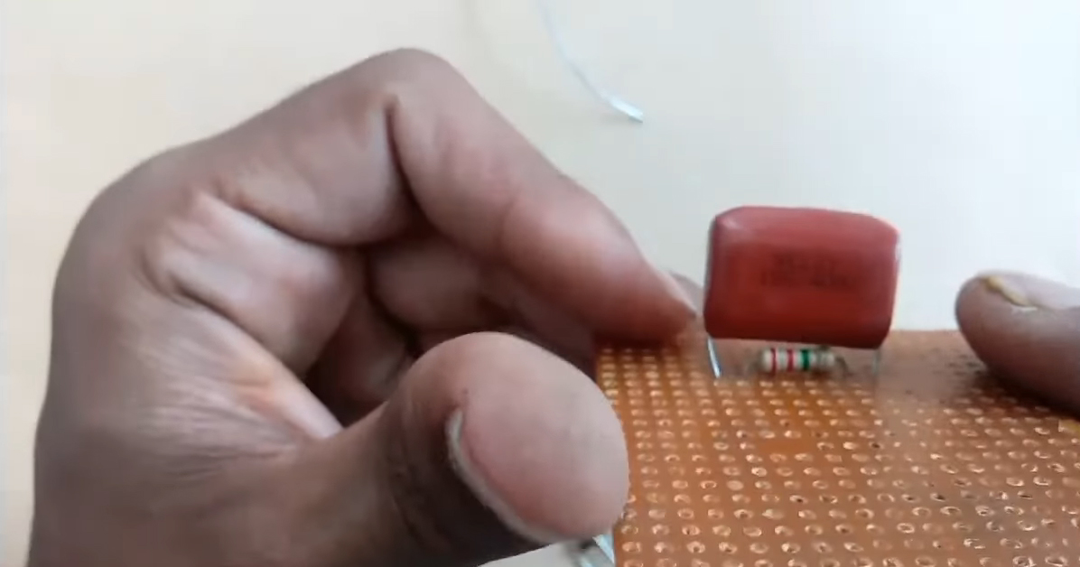
The heart of this transformerless power supply is an X-rated Capacitor. It is a ceramic metalized polypropylene film capacitor. X-Rated capacitors are usually joined in series with any live AC line in order to drop AC voltage. They are also connected from Line to neutral in some circuits. This then helps to block any electrical noise from entering the circuit.
Hardware Components
The following components are required to make Transformerless Power Supply
| S.No | Component | Value | Qty |
|---|---|---|---|
| 1) | Film Capacitor (ceramic) | 1.1uF/115J/400V | 1 |
| 2) | Diodes | 1N4007 | 4 |
| 3) | AC Wall outlet | 220V | 1 |
| 4) | AVO Meter | – | 1 |
| 5) | Capacitor | 220uF/63V | 1 |
| 6) | Resistors | 2.2M Ohms, 100K Ohms, 680 Ohms | 3 |
| 7) | Breadboard/Veroboard | – | 1 |
| 8) | Soldering Iron | 45W – 60W | 1 |
| 9) | Soldering wire with Flux | – | 1 |
| 10) | Jumper Wires | – | As per need |
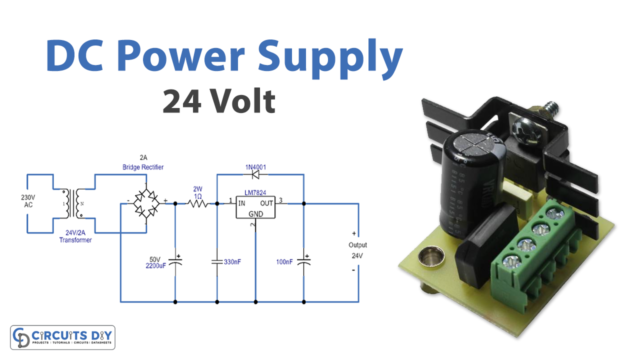
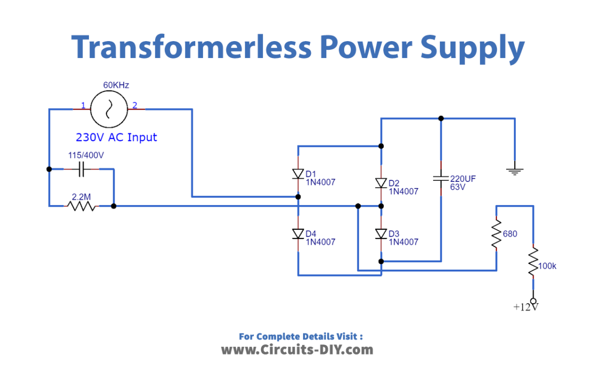
Transformerless Power Supply Circuit
Steps
Be sure to follow the steps as shown in the video above.
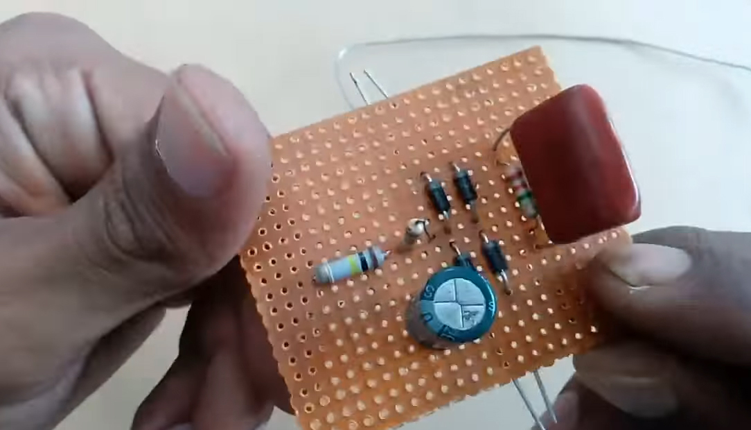
1) Solder the 2.2M Resistor on the Vero board.
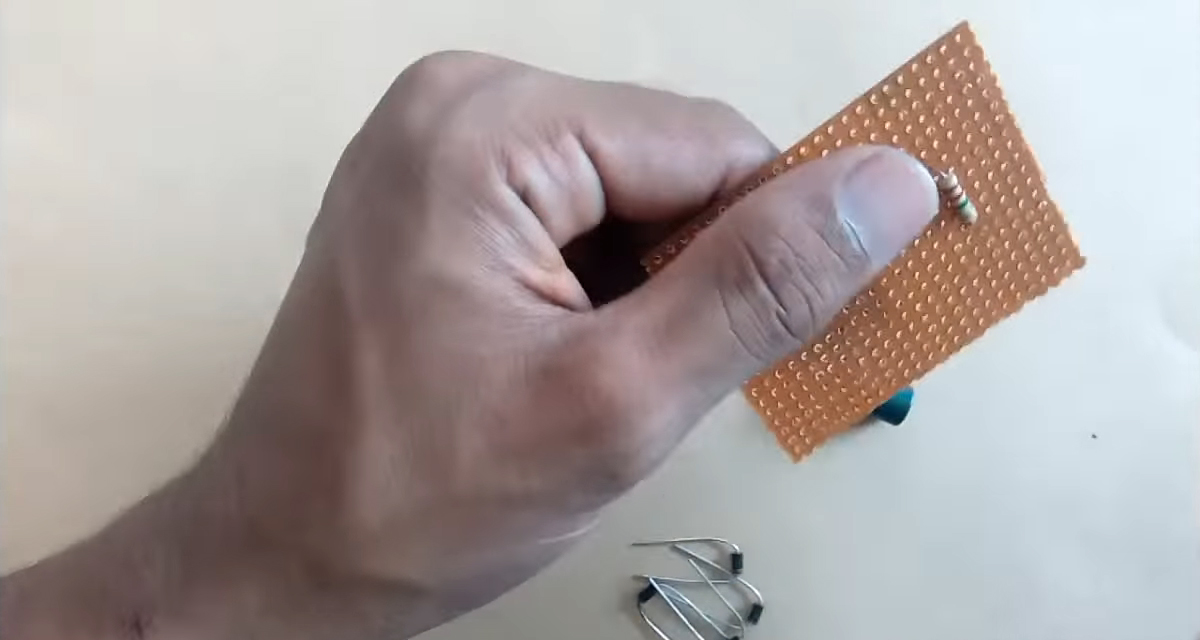
2) Solder the 1.1uF Film Capacitor in parallel to the 2.2M Resistor.
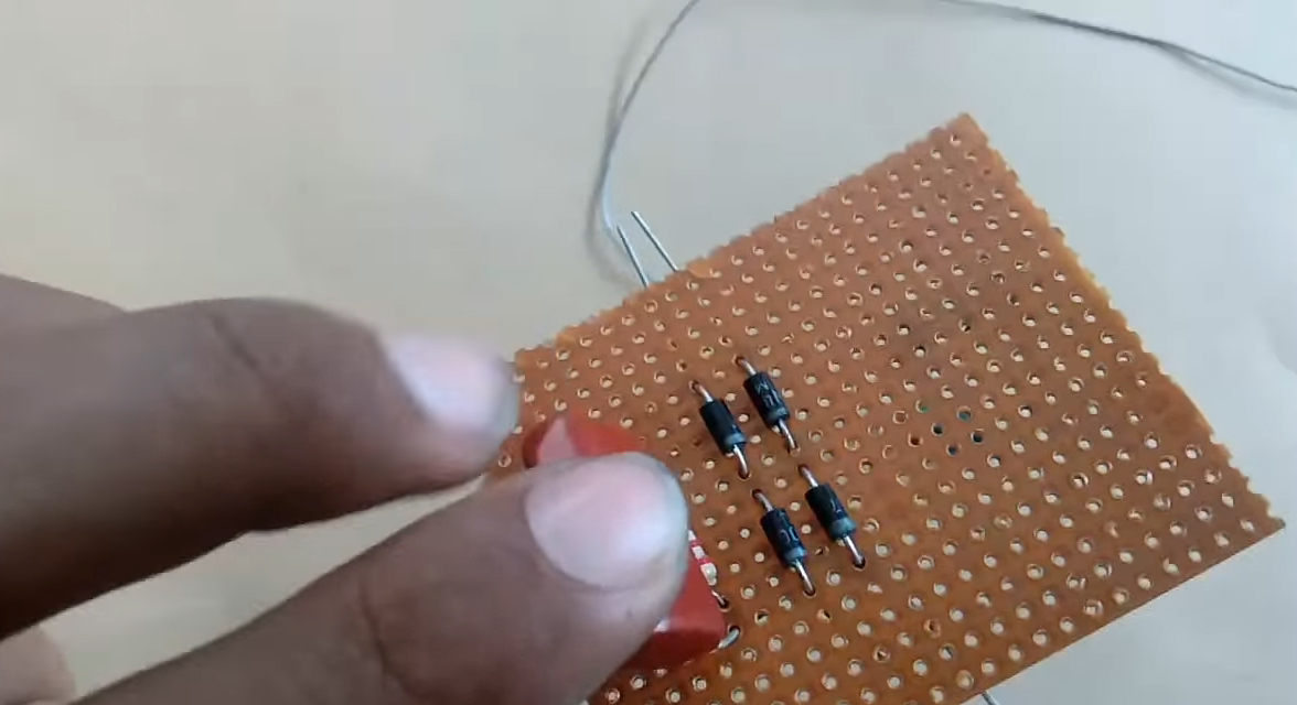
3) Solder the 4 diodes (1N4007) on the Veroboard.
4) Solder a 680 Ohm resistor at the output of the rectifier bridge.
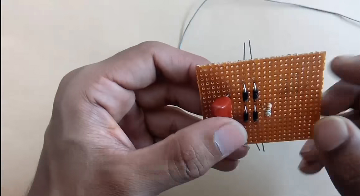
5) Solder a 100K Ohm resistor in series with a 680 Ohm resistor
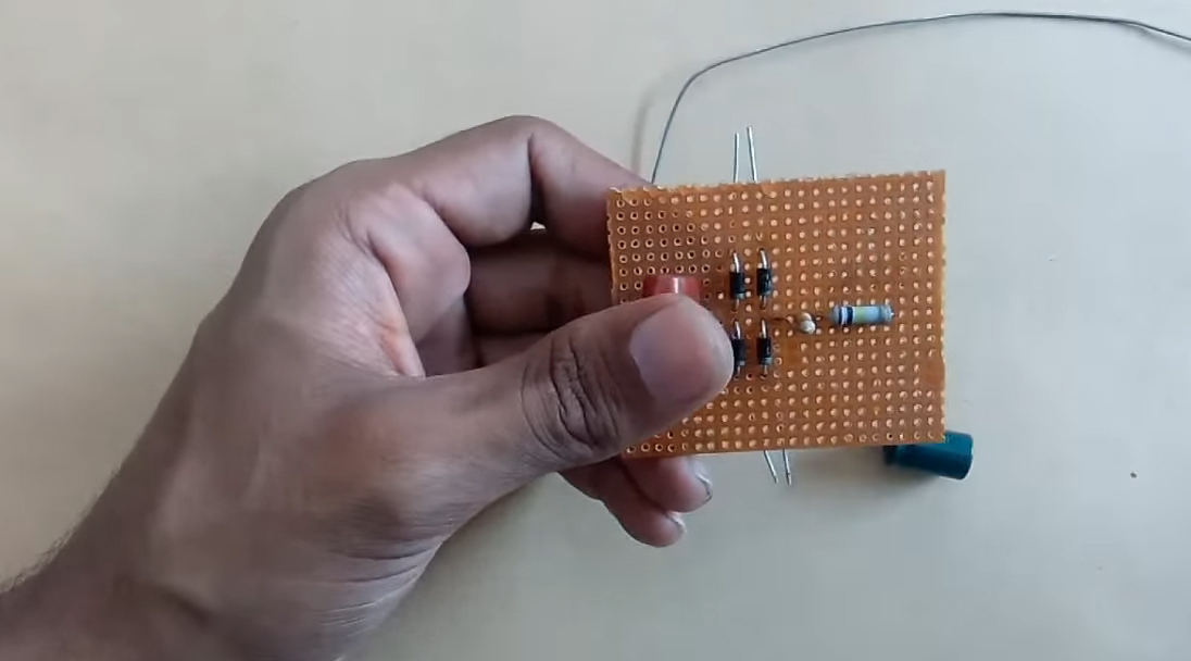
6) Solder a 220uF capacitor in parallel to the rectifier bridge.
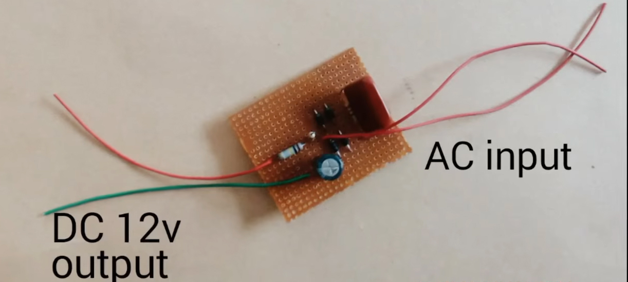
7) Solder input & output connectors to the circuit.
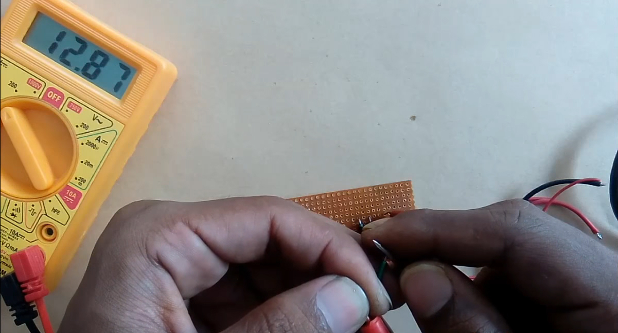
8) Test & inspect the circuit using a multimeter.
Working Explanation
The working of this circuit is as follows, an input supply of 220V AC is provided to the circuit. The X-rated capacitor (1.1uF) drops the voltage to the desired voltage range (12V), here, A 2.2M Ohm resistor is connected in parallel to the Capacitor, to discharge the stored current in the capacitor when the circuit is off, thus preventing electric shock. This resistance is called Bleeder resistance.
The low AC signal is then sent to a bridge rectifier (combination of 4 diodes) which converts the AC Signal into a rippling DC. The DC signal then passes through a smoothing capacitor (220uF) before moving toward the output. Only use resistors with a wattage rating of 1W or higher otherwise the resistors might burn out after some time.
Application
- We are usually used to power small electronic projects.
- It can also serve as a test bench power supply for small academic projects.