Introduction:
The power electronics converts are basically designed to convert the electrical energy from one form into another, it deals with the semiconducting materials and the energy storing devices. These power converters play a major role in real-world applications. The power converters are mainly divided into six types that is AC-DC converters, AC-AC converters, DC-DC converters, DC-AC converters, Diode rectifiers, and static switches. All these types of power converters occupy different importance according to their need in different sectors.
The inverters are the type of power converters that convert the DC signal at the input to the AC signal at their output, the output AC signal achieved is generally equal to the mains supply voltage. We can build inverters at home using simple electrical components to control low-power appliances.

Hardware Components
The following components are required to make the Inverter Circuit
| S.no | Component | Value | Qty |
|---|---|---|---|
| 1. | IC | NE555 timer | 1 |
| 2. | NPN Transistor | TIP41A | 1 |
| 3. | PNP Transistor | TIP42A | 1 |
| 4. | Transformer | 230V AC/ 9V AC | 1 |
| 5. | Variable Resistor | 50KΩ | 1 |
| 6. | Capacitor | 0.1μF, 0.01μF, 220μF | 1 |
| 7. | Resistor | 10KΩ, 100KΩ, 100Ω | 1 |
NE555 IC Pinout

For a detailed description of pinout, dimension features, and specifications download the datasheet of NE555 IC
TIP41A Pinout
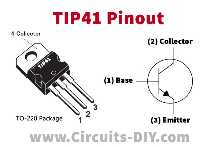
For a detailed description of pinout, dimension features, and specifications download the datasheet of TIP41A
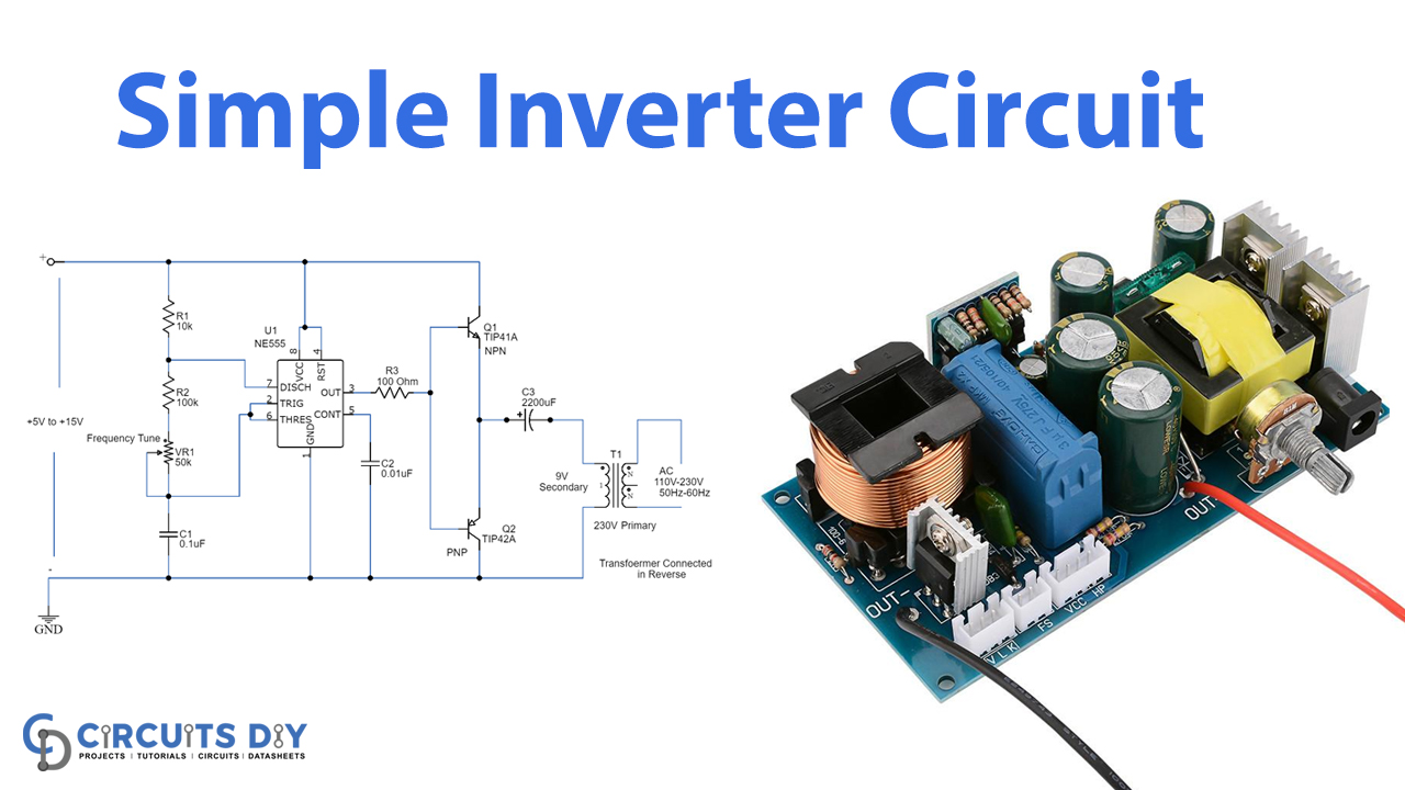
Inverter Circuit
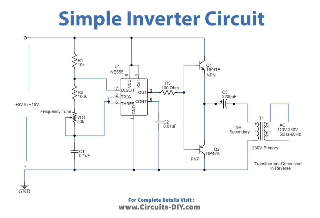
Working Explanation
The 555 timer IC is used as the key component which is configured as an Astable multivibrator to provide continuous switching pulses. The transformer has 230V/9V is used inverted to act as a step-up transformer and is derived by the two transistors TIP41A (NPN) and TIP42A (PNP). The input supply voltage is 5V to 15V DC and the output achieved is 110V to 230V AC with 50-60 Hz frequency, although it is not a pure sine wave.
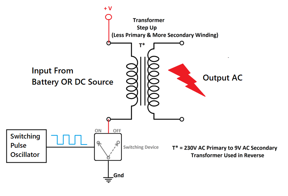
The two transistors provide a pulsating signal to the primary coil of the transformer at one end while the other end is connected to the switching transistor which is derived by the 50Hz frequency. When the switch is ON the transformer receives a pulse or else the primary is disconnected from the source. This switching action provides a discrete DC pulse to the transformer which is circulated in the windings developing magnetic flux This is due to the electromagnetic induction induced in the secondary windings and due to the more coils, higher EMF is induced thus the output is stepped up AC.
The formula for frequency is given below:
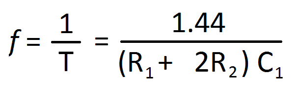
The heat sink is recommended to avoid the heating of transistors.
How does Switching Inverter work?
Uses:
The inverters are widely applicable for different applications:
- The major application is the solar power converters because solar power is DC power that needs to be converted into an AC source.
- It is used in UPS to provide AC sources through the battery.
- It might be used as an independent device as well.
- Inverters are also used in AC drives to control the speed of motors.