Before the invention of LED lights, fluorescent lamps existed everywhere. They are still highly in use. The fluorescent lamp is a mercury gas discharge lamp that uses fluorescence to generate light. The lamp is used pretty much everywhere, from home to offices, from school to industries. Hence, every place used fluorescent lamps. These lamps must need a driver circuit that can maintain their turning on and off. So, in this article, we will make a lamp driver circuit for fluorescent lamps.
To make this simple circuit NE555 IC works as a central element. A Step-up transformer is also used. So, try to make the circuit on a Vero board or good quality PCB board. Use a heat sink for the transistor. Use a 12V DC power supply to turn ON the circuit.
Hardware Required
| S.no | Component | Value | Qty |
|---|---|---|---|
| 1. | Vero/ PCB Board | – | 1 |
| 2. | Timer IC | NE555 | 1 |
| 3. | Potentiometer | 4.7K | 1 |
| 4. | DC | 12V | 1 |
| 5. | Resistors | 1.5K | 2 |
| 6. | Step-up transformer | – | 1 |
| 7. | Power Transistor | BD243C | 1 |
| 8. | Capacitor | 100nf | 1 |
| 9. | lamp | – | 1 |
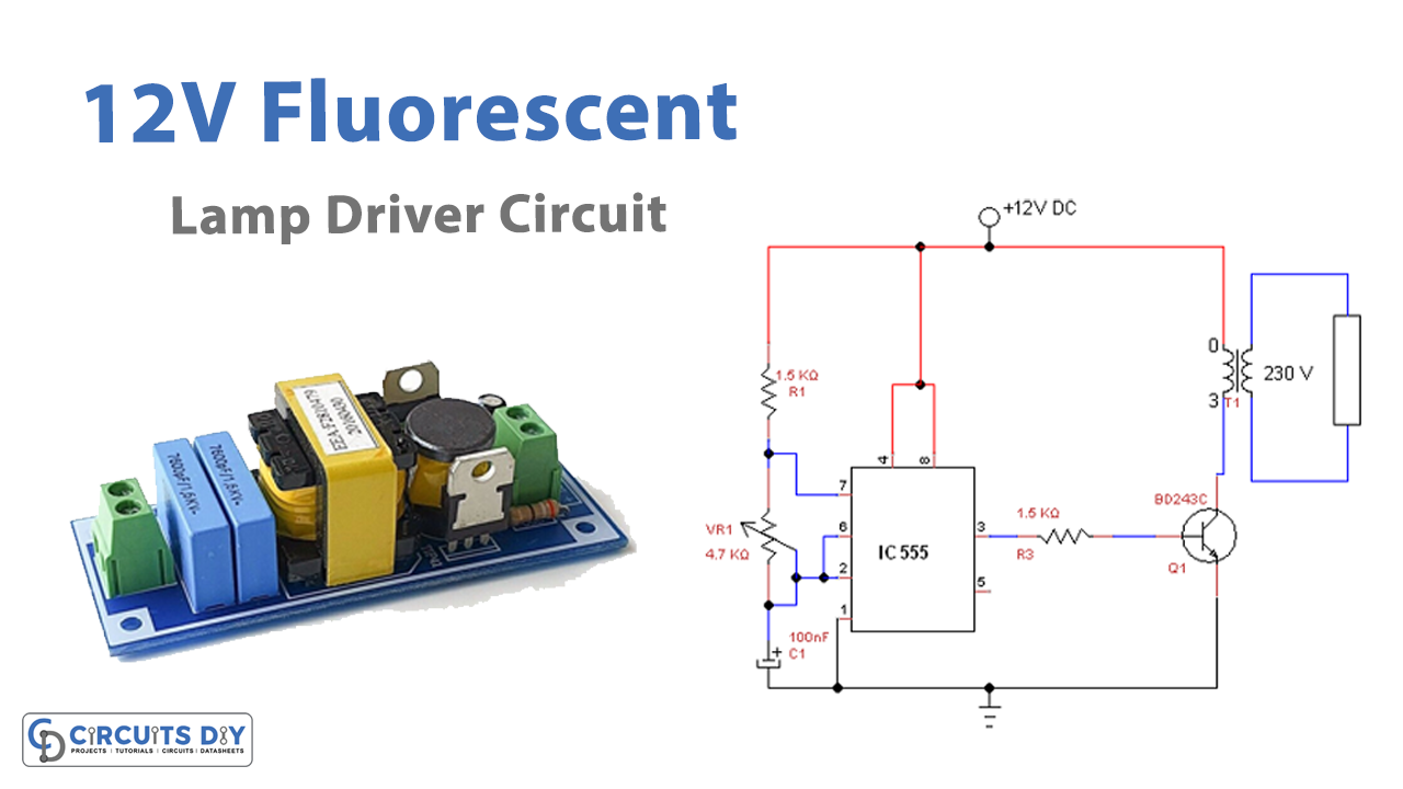
Circuit Diagram

Working Explanation
Here NE555 timer IC is working as an astable multivibrator. The output pulses of the IC get amplified when given to the transistor. Then, the transformer step-ups the voltage coming from the collector of the transistor. Use a 5 Watt transformer for this purpose. This drives the operating lamp. The potentiometer R2 used in the circuit is wired to adjust the supply voltage.
Application and Uses
The main purpose of this circuit is to drive the fluorescent lamp. But, with further modification, it can be used for different appliances.