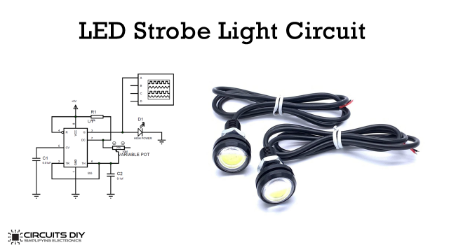
Pulse-width modulation (PWM) is a modulation technique that is used by most communication systems for encoding the amplitude of a signal right into a pulse width or duration of another signal, usually a carrier signal, for transmission. PWM is an important feature of every microcontroller due to its requirement for controlling many devices in almost every field of electronics.
Sometimes we do not use a microcontroller in our applications and if we need to generate PWM without a microcontroller then we prefer some general-purpose ICs like timers or pulse generators, etc. In this tutorial, we will show you how you can make a PWM generator circuit using a 555 Timer IC and some basic electronics components.

Hardware Components:
The following components are required to make PWM Generator Circuit
| S. NO | Component | Value | Qty |
|---|---|---|---|
| 1. | Breadboard | – | 1 |
| 2. | Battery | 9v | 1 |
| 3. | Connecting Wires | – | 1 |
| 4. | IC | NE555 Timer | 1 |
| 5. | Diode | 1N4007 | 2 |
| 6. | Capacitor | 0.01uF | 1 |
| 7. | Variable Resistor | 10k ohm | 1 |
| 8. | Resistors | 100 ohms, 1k ohm | 1, 1 |
| 9. | LED | 5mm | 1 |
555 IC Pinout

For a detailed description of pinout, dimension features, and specifications download the datasheet of 555 Timer
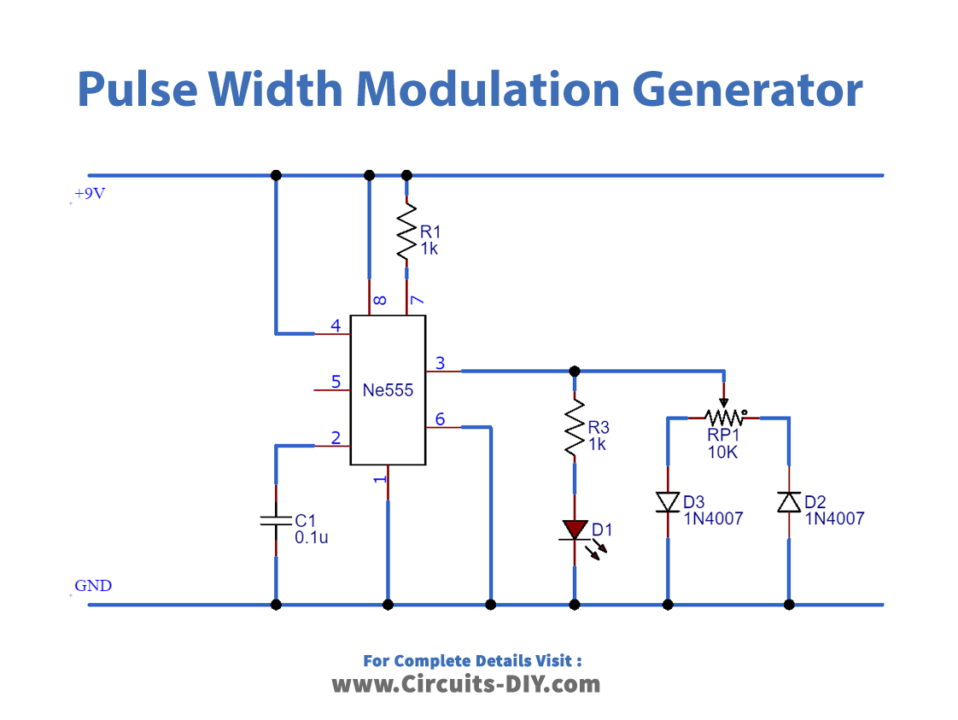
Circuit Diagram
Connection
- Place the 555 timer IC on the breadboard and connect Pin 8 to VCC and Pin 1 to GND.
- Use a jumper wire, to connect Pin 2 and Pin 6 together.
- Connect Pin 4 to VCC.
- Use the 0.01uF Capacitor to connect Pin 2 to GND.
- Connect an LED with a 100 Ω Resistor to Pin 3.
- Use a 1K Resistor to connect Pin 7 to VCC.
- Connect the Middle Pin of the variable resistor to Pin 3 of the IC.
- Connect diodes to the variable resistor, as shown in the circuit diagram.
Working Explanation
In this circuit, we will use a 555-timer IC for generating PWM. The 555 timers will operate in astable mode and generate continuous square waves at the output. To change the duty cycle of the output signal we will change the resistance by using the variable resistor. The LED connected to the output indicates the duty cycle of the output PWM with a fading effect. If you want to view the output on an oscilloscope then connect the probe of the oscilloscope in parallel with the LED. The output of the 555 timers can supply a maximum current of 200mA to the load. So if the motor that we want to control exceeds this rating then use a transistor or a MOSFET for driving the motor.
Application
- PWM circuit is widely used for controlling motors and lights.
- PWM is used in Telecommunications for encoding purposes.
- The computer Motherboard requires PWM Signals to control the heat generated by the board.