These security alarms are exceptionally valuable to discourage Bulgari from shopping malls, banks, jewelry retailers, and so on.
Therefore, the circuit utilizes a light-dependent resistor or LDR to detect the laser beam. At the point when laser light falls on the LDR sensor, the resistance of the sensor diminishes, which leads to initiating a buzzer or bell to give an alarm to the client. This astounding project is appropriate for providing a security framework for storage spaces, money encloses, or lockers of banks, shopping centers, and jewelry shops.
This DIY project aims to set the lockers of shopping malls, banks, or jewelry shops with laser light beams. These laser lights are likewise advisable to connect with the locker doors. Hence, when a thief opens the money box or locker, the appended laser light gets initiated. Subsequently, when the laser light falls on the LDR circuit attached to the vault triggers the buzzer and shows a robbery attempt. Instead of a laser, any LED of a Fluorescent light beam is also used to activate the buzzer circuit. Additionally, the circuit utilizes an NE555 timer IC, an LDR, a piezo buzzer, a Laser light, and a few other components.

Hardware Components
The following components are required to make a Laser Light Alarm Circuit
| S.no | Components | Value | Qty |
|---|---|---|---|
| 1. | IC | NE555 Timer | 1 |
| 2. | Potentiometer | 15k | 1 |
| 3. | Piezo buzzer | – | 1 |
| 4. | LDR | – | 1 |
| 5. | Laser Light or bulb | – | 1 |
| 6. | Battery | 6 Volts | 1 |
| 7. | Electrolytic Capacitor | 1000uF | 1 |
| 8. | Ceramic Capacitor | 0.01uF | 1 |
NE555 IC Pinout

For a detailed description of pinout, dimension features, and specifications download the datasheet of 555 Timer
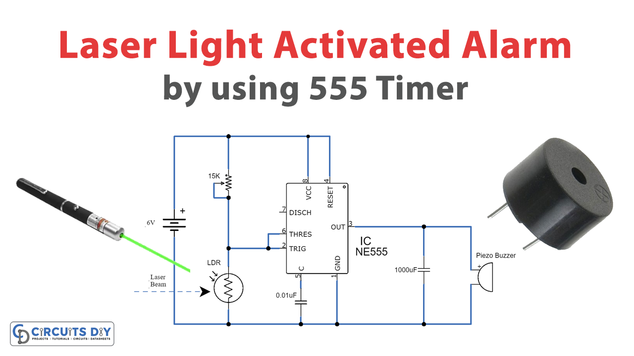
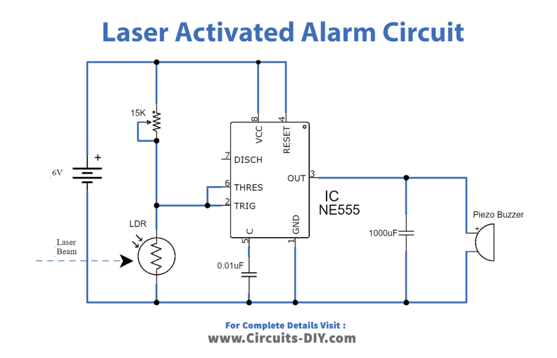
Laser Light Alarm Circuit
Working Explanation
The circuit operates in such a way that, at the point when the laser beam falls on the LDR surface, its resistance diminishes because of which the 555 IC triggers and charges the 1000uF electrolytic capacitor and actuates the piezo ringer. Moreover, the piezo buzzer will stay dynamic through a 1000uF capacitor for a few moments after the yield of 555 IC goes low.
The circuit requires a simple setting and alteration, so the LDR will just get laser light and no other light like sun or room light. Because the circuit won’t work appropriately, then it will bring light from different sources. Thus, the circuit must be in an enclosed box, where no other light can affect the circuit operation. Moreover, the working voltage of the circuit is 6V DC, yet it can likewise be worked with any voltage between 4.5V to 12V DC. The affectability of the circuit can be balanced with a 15K variable resistor.
In the future, this project can be created by utilizing a GSM modem and a microcontroller. This modem can be interfaced to send an SMS to the client if there should be an occurrence of robbery.
Applications and Uses
- Use in security systems.