Introduction
Memory plays a crucial role in digital electronic circuits and devices. Just like a human brain, digital circuits need memory to store and process data. Take an example of a computer, Computer has memory which is the storage space, where the data or information which are to be processed and instructions for processing are stored. So, to understand the concept of digital memories, in this tutorial, we have decided to make a “Bit Memory Circuit”
Though we can make it through different memory circuits with different components. However, we are making this one-bit memory circuit using IC NE555. But let us first discuss what is a one-bit memory cell.
What is a One Bit Memory Cell?
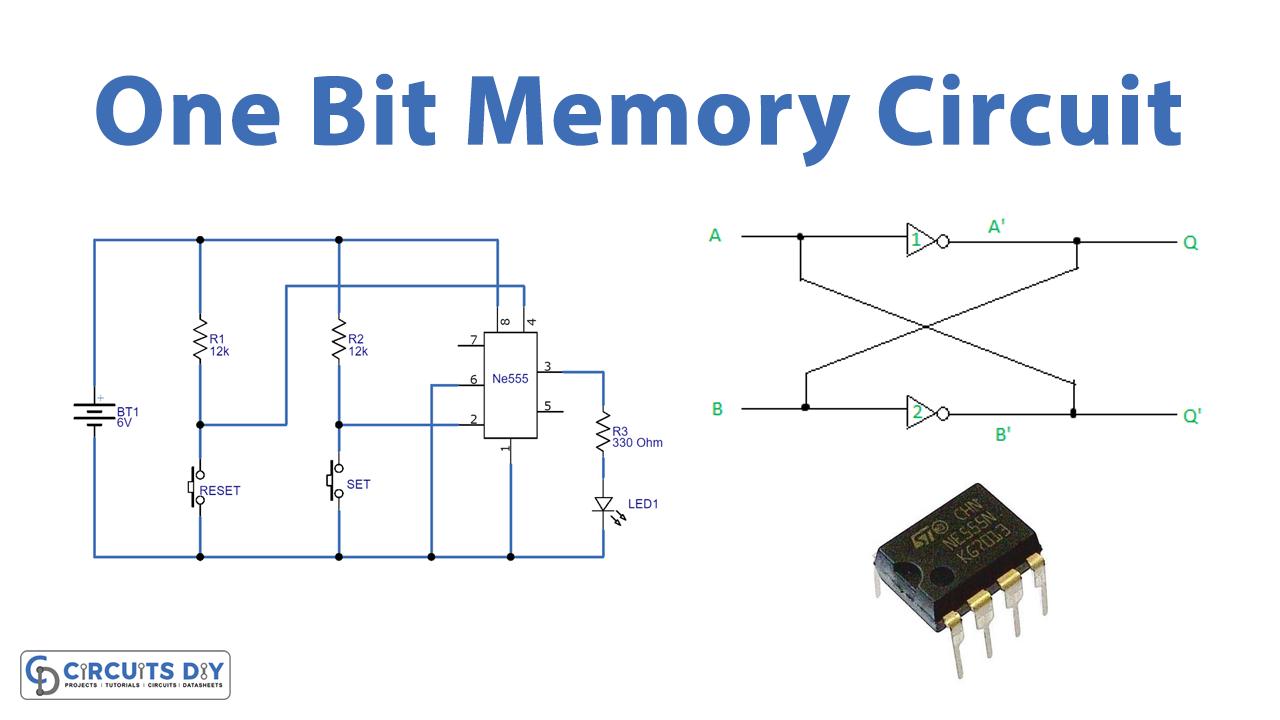
The one-bit memory cell is an electronic circuit that stores the high and low logic states in binary forms. This means, for logic high, it stores 1 and for logic low, it stores 0. One Bit memory cell is also known as the Basic Bistable element. It usually has two cross-coupled inverters, having two outputs. And, therefore we can also one-bit memory circuit by utilizing NAND gates. But, in this article, our main focus is to create this circuit using a 555 timer IC.
Hardware Required
| S.no | Component | Value | Qty |
|---|---|---|---|
| 1. | IC | NE555 Timer | 1 |
| 2. | LED | – | 1 |
| 3. | Push-button | – | 2 |
| 4. | Resistor | 12KΩ, 330Ω | 2, 1 |
| 5. | Breadboard, hookup wires | – | – |
| 6. | Battery | 6V | 1 |
| 7. | 2-Pin Connector | – | 1 |
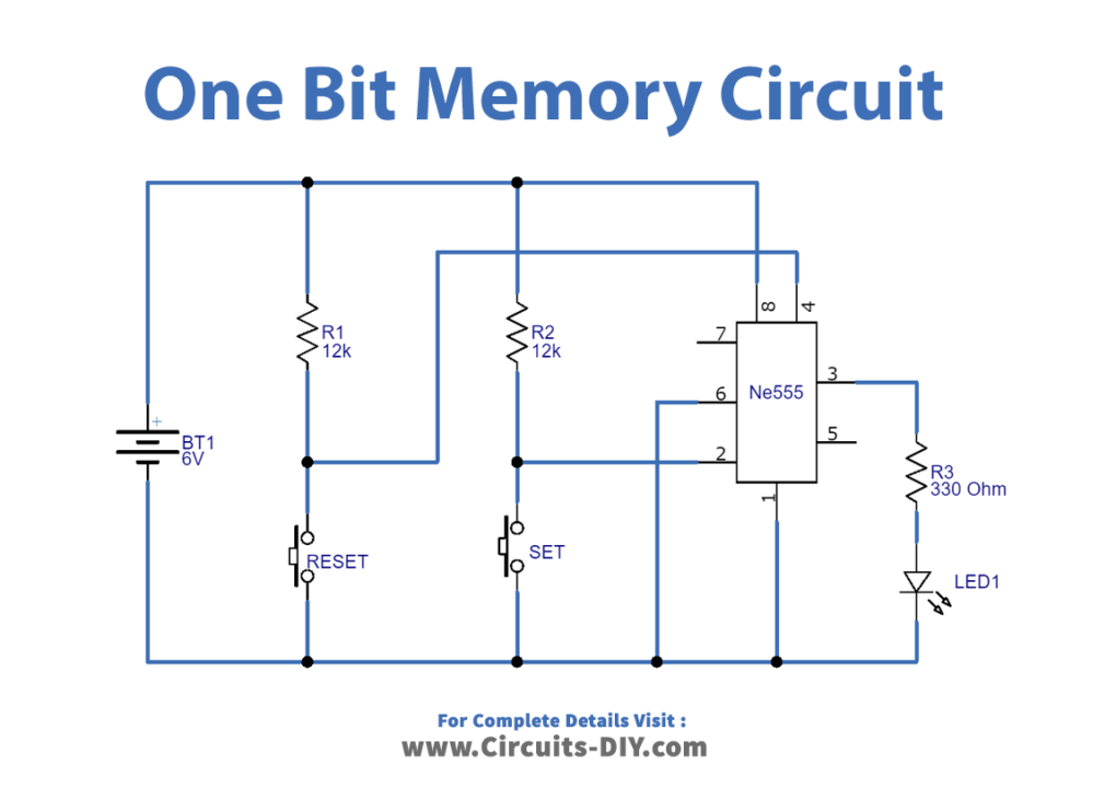
Circuit Diagram
Working Explanation
In this bit Memory Circuit, we are using 555 timer IC reset pin and trigger pin connected to ground supply with the help of push-button. So, when you press the push button ground supply starts to flow to the corresponding pin. We connected the threshold pin to the ground, and we connect the output pin with LED that will indicate the stored bit.
When you press the set button it stored the logic 1 bit in the internal flip-flop of IC 555. When you press the Reset button it stored the logic 0 bit in the internal flip-flop of IC 555.
Thus, If the LED glows, it would represent logic 1, If it is in off condition and doesn’t glow, then it would represent logic 0.
Application and Uses
- We can utilize this in small digital electronic circuits.