In electronics & electrical systems, faults are very common. The most commonly appearing fault is due to a discontinued connection or open circuit. To rectify such kinds of faults, one could go through all the lines to identify the fault itself. Though, this method of fault search is generally replaced by continuity testing equipment. So in this tutorial, we are going to make a “Continuity Tester Circuit using 555 Timer IC”
The heart of this circuit is a NE555 Timer IC. The IC possesses an oscillation frequency ranging from 670 to 680 Hz. Here, this NE555 timer acts as an astable multivibrator An astable multivibrator is a free-running oscillator that switches continuously between its two unstable states. With no external signal applied, the transistors alternately switch from cutoff to saturation state at a frequency that RC time constants of the coupling circuit determine. If these time constants are equal (R and C are equal) then a square wave will generate with a frequency of 1/1.4 RxC. Hence, an astable multivibrator is also a pulse generator or a square wave generator.
Hardware Components
The following components are required to make the Continuity Tester Circuit
| S. No | Component | Value | Qty |
|---|---|---|---|
| 1. | IC | NE555 Timer | 1 |
| 2. | Resistors | 1k, 10k, 100 ohms | 1, 1, 1 |
| 3. | Capacitor | (100nF) | 1 |
| 4. | PNP Transistor | 2N3906 | 2 |
| 5. | Power Supply | 9v | 1 |
| 6. | Testing Probes | 1 |
555 Timer Pinout

For a detailed description of pinout, dimension features, and specifications download the datasheet of 555 Timer
Continuity Tester Circuit
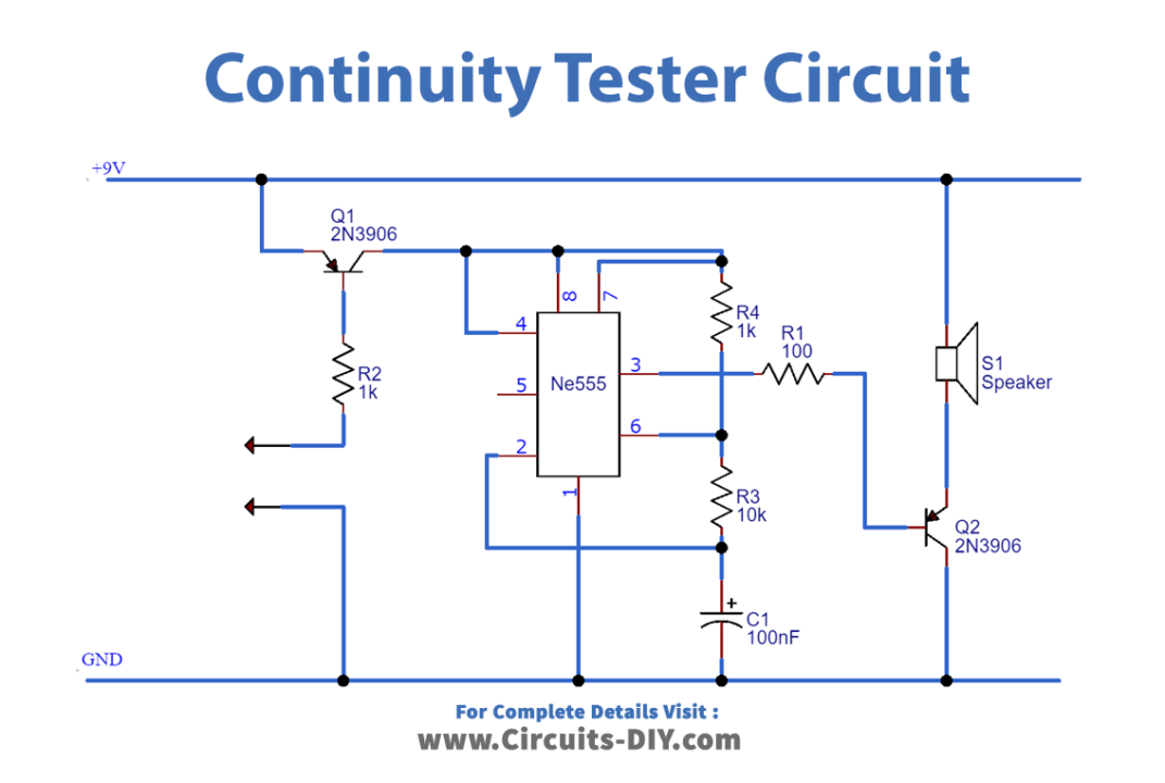
Working Explanation
Here, the base of the PNP transistor and a terminal from the ground are used as a pair for continuity testing. When these two terminals are connected together or flow through a short circuit, the PNP transistor turns on and delivers power to the timer and the timer gives pulses to the NPN transistor (2N3904) to drive the speaker. So when these two terminals are shorted or are driven through some resistance we get noise. This noise will verify that there is continuity in the line.
When the pair is connected across an open-circuited line, there will be no signal on the base of the PNP transistor & it will be off. So no power will go to the timer and there will be no sound, indicating that it’s an open circuit line.
Applications
- Commonly used in electrical test equipment such as AVO meters/multimeters to determine if an electrical path can be established between two points of a circuit.