An ON Delay Timer Circuit is a simple electronic circuit, which often serves to initiate time delays in different switching applications. This delay of a few minutes or seconds at times becomes the deciding factor in the success of an industrial process. In case the time delay accidentally fluctuates due to a malfunction, the processor device in question could become damaged. So, in this project, we will build a simple ON Delay timer circuit using three 2N3904 NPN Transistors.
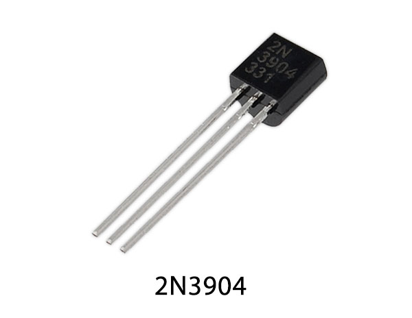
2N3904 is an NPN transistor, hence the collector and emitter will remain open when the base pin is at the ground and will be short when an input signal trigger goes to the base pin. 2N3904 has a gain value of 300. The max threshold of current that could flow through the collector pin is 200mA. Hence, we cannot connect loads that consume more than 200mA using this transistor. In order to bias a transistor, we have to supply current to the base pin, The current to which should be limited to 5mA.
Hardware Components
The following components are required to make the On Delay Timer Circuit
| S.no | Component | Value | Qty |
|---|---|---|---|
| 1. | Transistor | 2N3904 | 3 |
| 2. | SPDT Relay | 12V/5V | 1 |
| 3. | Resistors | 470K, 47K | 1 |
| 4. | Diode | 1N4007 | 1 |
| 5. | Electrolytic Capacitor | 470uF | 1 |
| 6. | Breadboard | 1 | |
| 7. | Battery | 9V | 1 |
| 8. | Battery Clips | – | 1 |
| 9. | Push button | – | 1 |
| 10. | Connecting Wires | – | 1 |
2N3904 Pinout
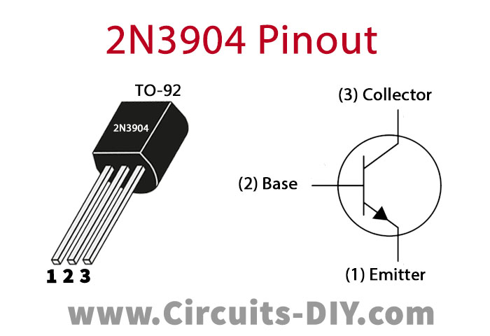
For a detailed description of pinout, dimension features, and specifications download the datasheet of 2N3904
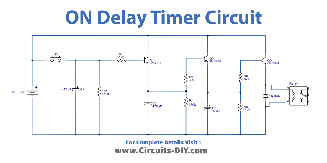
On Delay Timer Circuit
Working Explanation
Generally speaking, this circuit is an enhanced version of a single transistor time delay circuit. On pressing the pushbutton (S1) the transistor Q1 receives a control signal at its base through a 47K resistor. this triggers the Q1 switch and charges capacitors C1 & C2.
Now, on releasing the pushbutton. The Capacitor C2 discharges after a delay & triggers transistor Q2, charging capacitor C3 which introduces a further delay. After this, the capacitor C3 discharges and triggers the transistor Q3. Subsequently, the relay coil energizes & makes the SPDT switch, in order to power an AC or DC load. Here, a 1N4007 diode protects the SPDT relay from shorts. The time delay of this circuit can be increased or decreased by turning the values of the capacitors C1- C3 & by using a transistor with a variable switching time.
Applications
- They generally serve as a stabilizing protection scheme for surge-sensitive appliances such as UPS, Fridge, Air Conditioners & Deep Freezers.
- Also used in devices such as Power banks, Stopwatches, Coffee makers, etc.