Introduction:
Counters play an important part in digital electronics. The basic application of counters is to record the number of occurrences of an event. Counters can not only use for the counting operation but the measurement of frequency and time. Mathematical operations can be performed using this tool, it can increment and decrement the value of the operator depending on its previous value.
The counters are divided into two types:
Asynchronous counters: In asynchronous counters, the change in the transition state is independent of the input clock signal. They are also called ripple-counters.
Synchronous counters: In synchronous counters, the input clock signal changes the state of transition.
These counters are applicable in many practical applications. The simple circuit and its working principle are described in detail in this post.

Hardware Components
The following components are required to make Binary Counter Circuit
| S.no | Component | Value | Qty |
|---|---|---|---|
| 1. | IC | HD74HC4040 | 1 |
| 2. | IC | NE555 timer | 1 |
| 3. | LEDs | – | 8 |
| 4. | Ceramic Capacitor | 0.1uF | 1 |
| 5. | Electrolytic Capacitor | 10uF | 1 |
| 6. | Resistor | 1KΩ, 10KΩ, 220Ω | 2, 1, 1 |
| 7. | Battery | 6V | 1 |
NE555 IC Pinout

For a detailed description of pinout, dimension features, and specifications download the datasheet of 555 Timer
Binary Counter Circuit
Construction & Working:
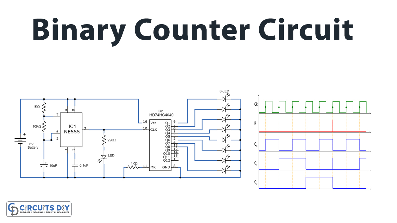
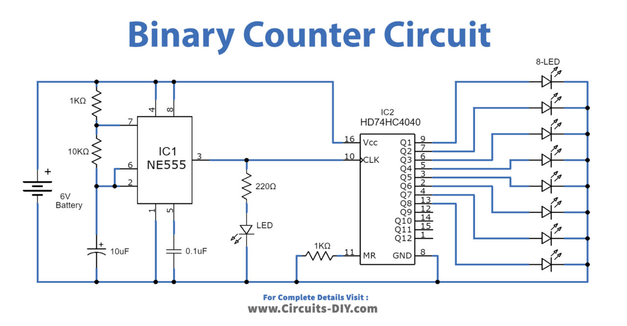
The circuit is divided into two parts clock pulse generator and the counter. Both the steps of the circuit are explained in detail.
The first part is the clock generator for which we have used a 555 timer IC. The IC is configured in Astable multivibrator mode to get a continuous square wave signal as an output. The value of the output can be varied using the resistor R2 connected to the threshold and trigger terminal coupled together while the LED connected to the output terminal through a resistor indicates the status of the output pulse.
The next part is the counter, for which the IC HD74HC4040 is used which increments the counter value from Q0 to Q11 for each input falling edge. The eight LEDs used are the indicator of 8-bit binary output. The RESET pin is grounded during the counting.
Note: Any ripple counter IC can be used in place of the above-used IC to make the counter (up or down) by following the specifications sheet. Any regulated DC power source or a 6V battery can be used as a power source.
Applications & Uses:
Counters find its applications in a number of digital electronic devices. Some uses are mentioned under:
- It is used in digital clocks for measuring time.
- It is used in frequency counters as a frequency measuring element.
- Triangular wave generator circuits can be built using counters.
- It is also applicable in analog to digital converters.
- There are various other uses of digital counters as well.