Clap switch circuits work by detecting the sound of a clap, whistle, or any other sound of the same pitch. This electronic mini-project has the ability to detect a high pitch as that of a clap with the help of an Electret microphone and turn the circuit ON or OFF accordingly. The output of clap switch circuits can be connected to any DC or AC appliance for the ON/OFF operation.
Hardware Components
The following components are required to make Clap Switch Circuit
| S.no | Component | Value | Qty |
|---|---|---|---|
| 1. | Transistor | 2N4401 | 2 |
| 2. | SPDT Relay | 9V/12V | 1 |
| 3. | LEDs | – | 1 |
| 4. | Resistor | 470Ω, 1KΩ, 4.7KΩ, 1MΩ | 2,1,1,1 |
| 5. | Ceramic Capacitor | 0.1µF | 2 |
| 6. | Electrolytic Capacitor | 47µF | 1 |
| 7. | Diode | 1N4007 | 1 |
| 8. | Breadboard | – | 1 |
| 9. | Connecting Wires | – | 1 |
| 10. | Battery | 9V to 12V | 1 |
2N4401 Pinout
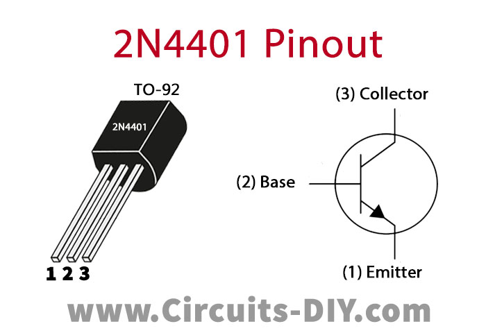
For a detailed description of pinout, dimension features, and specifications download the datasheet of 2N4401
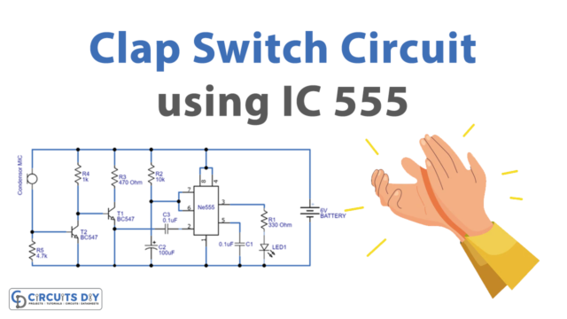
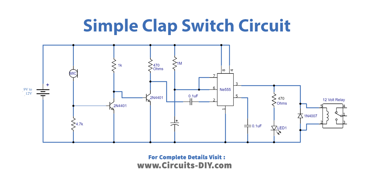
Clap Switch Circuit
Working Explanation
There are two parts to the circuit. One is the transistor part where amplification is done. Whereas, the other one is the IC NE555 which is responsible for generating pulse to the LED making it turn ON/OFF. Here in the circuit, the timer IC NE555 is working in its monostable mode. Additionally, in a monostable mode of operation, the NE555 outputs a single pulse for a desired period of time.
When a sound with a similar pitch as a clap is heard by the electret microphone, it converts this sound energy into an electrical signal. This electrical signal is then going through the two 2N4401 transistors, thus amplifying this signal. Now, this amplified signal is the input to the IC PIN 02. The monostable mode of operation of the IC outputs a HIGH at PIN 03, hence, lighting the LED and relay for a certain period of time. This ON time is set using the capacitor Cx in the circuit that by increasing or decreasing the value of Cx, time duration can be increased or decreased, respectively. After the set time duration, the output PIN 03 of the IC goes LOW, and thus the LED is turned OFF.
The circuit operated at 9V to 12V of battery but it does as well operate at 5V or 6V. But, when operating the circuit at low voltage, make sure the relay is of the same voltage as well.