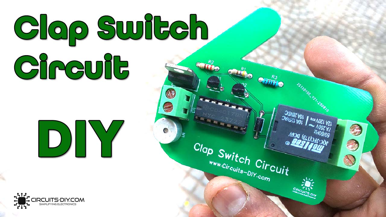
What is a Clap Switch Circuit?
A clap switch circuit allows you to achieve remote dynamic control of various devices by using the application of sound. They are used in home automation applications such as sound-activated LEDs & fans, that respond to a knock on the door. So, in this project, we will go through a step-by-step procedure on How To Make A Clap Switch Circuit using a Decade counter IC & a small no. of other components.
The heart of this Clap Switch Circuit is a CD4017 IC. A CD4017 IC is a 16-pin CMOS decade counter/Divider IC with 10 outputs. It is also known as the ‘Johnson 10 stage decade counter’. It has 10 decoded outputs that give output signals one by one in sequence when a clock signal from the clock input is given.
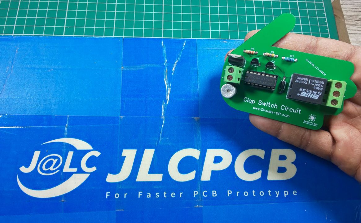
JLCPCB is the foremost PCB prototype & manufacturing company in china, providing us with the best service we have ever experienced regarding (Quality, Price Service & Time).
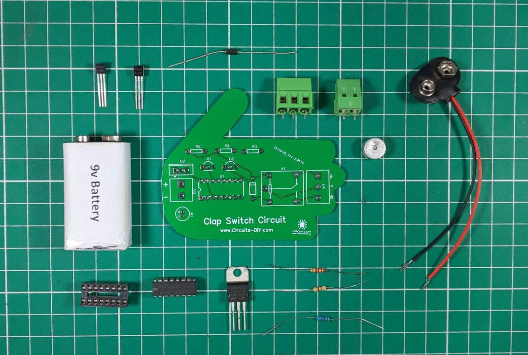
Hardware Components
The following components are required to make Clap Switch Circuit
| S.no | Component | Value | Qty |
|---|---|---|---|
| 1. | Decade Counter IC | CD4017 | 1 |
| 2. | Relay | 6V/SPDT | 1 |
| 3. | Transistor | BC547 | 2 |
| 4. | Condensor mic | – | 1 |
| 5. | filament lamp | 220V | 1 |
| 6 | Diode | 1N4007 | 1 |
| 7. | Regulator IC | LM7805 | 1 |
| 8. | Resistors | 22K, 1K, 470 Ohms | 3 |
| 9. | wall outlet with plug | 220V | 1 |
| 10. | Soldering Iron | 45W – 65W | 1 |
| 11. | Soldering wire with flux | – | 1 |
| 12. | Veroboard | – | 1 |
| 13. | DC Battery | 9v – 12v | 1 |
| 14. | Battery clip | – | 1 |
| 15. | Jumper wires | – | As per need |
CD4017 Pinout
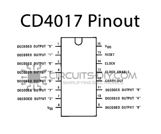
For a detailed description of pinout, dimension features, and specifications download the datasheet of 555 Timer CD4017
Clap Switch Circuit
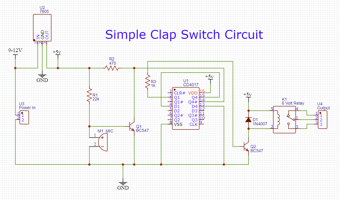
Working Explanation
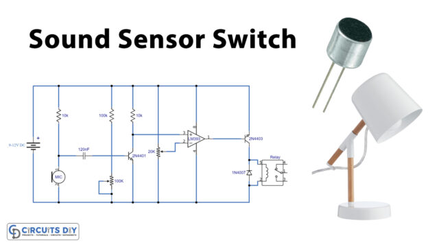
The working of this circuit is as follows, sound input is received through the condenser mic, and the mic converts the input sound signal into an electrical signal, which acts as a control signal to the base of the first BC547 transistor. The collector output from the transistor functions as the CLK Input for the CD4017 IC.
The output from pin 2 of the Decade counter serves as the control signal for the second BC547 transistor. The colletor output energizes the coil of the SPDT relay, which subsequently makes the coil & activates the secondary circuit connected to the relay. Always use an SPDT relay with a voltage rating comparable to the input supply (12V/9V/5V).
Applications
- It can be used in electrical appliances such as Tube Light, Fan, Radio or any other basic circuit which you want to turn ON & OFF only by sound.