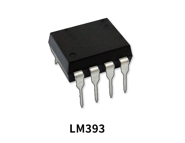
The LM393 is a dual independent accuracy voltage integrated circuit, run with a single (2V to 36V) or else a dual supply (±1V to ±18V). This IC comprises two independent voltage comparators to operate from only power supply more than a wide variety of voltages. The output transistor can drive loads up to 50V & 50mA which is suitable for driving most of the TTL, MOS, and RTL loads. The IC can also make the Load to be isolated from the system ground.
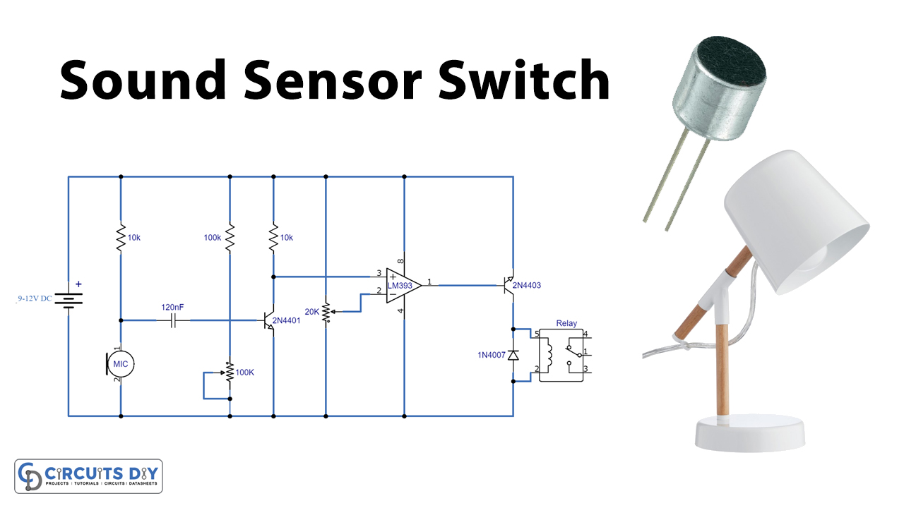
A sound sensor switch is a type of switching device that responds to an audio input. With a proper sound-activated switch, dynamic control by sound may be very useful, not just on robotic systems but also for home automation, for example, a sound-activated light responding to a knock on the door or a hand clap. So, in this project, we will build a simple sound sensor switch using the LM393N comparator IC.
Hardware Components
The following components are required to make Sound Sensor Switch Circuit
| S.no | Component | Value | Qty |
|---|---|---|---|
| 1. | Breadboard | – | 1 |
| 2. | Connecting Wires | – | 1 |
| 3. | Battery | 9v | 1 |
| 4. | IC | LM393N | 1 |
| 5. | Transistor | 2N4401, 2N4403 | 1 |
| 6. | DC Relay | – | 1 |
| 7. | IC | LM7805 | 1 |
| 8. | Diode | 1N4007 | 1 |
| 9. | Potentiometer | 20K,100K | 1,1 |
| 10. | Ceramic Capacitor | 120nF | 1 |
| 11. | Resistors | 100k, 10k | 1,1 |
| 12. | Condenser MIC | – | 1 |
LM393 Pinout
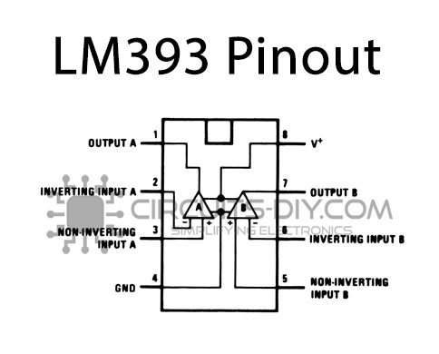
For a detailed description of pinout, dimension features, and specifications download the datasheet of LM393
2N4401 Pinout
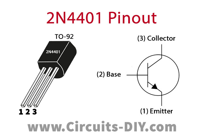
For a detailed description of pinout, dimension features, and specifications download the datasheet of 2N4401
2N4403 Pinout
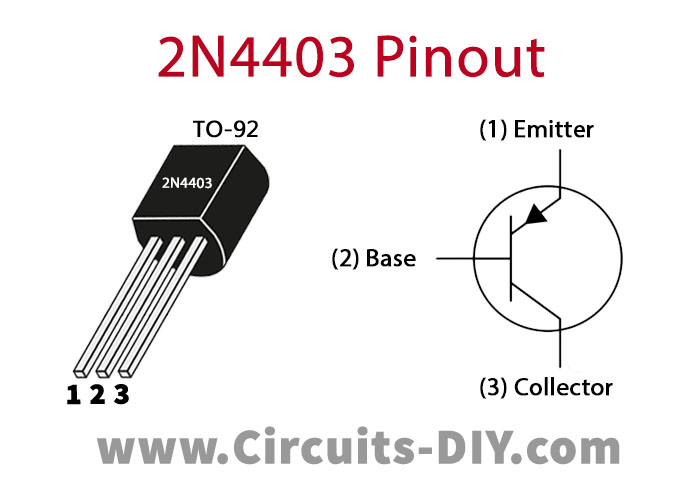
For a detailed description of pinout, dimension features, and specifications download the datasheet of 2N4403
Sound Sensor Switch Circuit

Working Explanation
The heart of this circuit is an LM393N comparator IC. In this circuit, we have used only one out of the two comparators. First, the audio input is taken from the electret microphone. Here a 120nF capacitor blocks the DC component of the audio, allowing only AC to flow to the transistor (2N4401). Now, this signal acts as a control signal to the base of the 2N4401 transistor, whose voltage level is controlled by a voltage divider pair.
The 2N4401 transistor amplifies the sound signal received by the electret microphone. The amplified signal is then fed to the LM393N voltage comparator IC and a further amplified signal is received at the output pin 8 of the IC. A 2N4403 PNP transistor is used at the output of the IC to drive an SPDT relay switch. The sensitivity of the circuit can be adjusted with the 100KΩ & 20KΩ variable resistors. The operating voltage of the circuit is 9V to 12V DC but it can also be operated on a low voltage (3V-6V). The SPDT relay should be in accordance with the operating voltage.
Applications
- A sound switch circuit is not just for turning LEDs ON and OFF, but it can be in use in any electric appliance such as Tube Light, Fan, Radio or any other basic circuit which you want to turn ON & OFF only by sound.