Introduction
We are living in an era, where we all want to save time and money. And, want to get better security. The night security light is for turning ON and OFF the light in the night automatically and making that area secure. It grasps the light intensity from the environment and discovers that it’s day overnight and works accordingly. Therefore, it uses the light-dependent resistor for this purpose.
The Night Security Light is not difficult to assemble. It uses LDR which changes its resistance according to the surroundings. When there is a day, means the light intensity is high, the resistance increases, hence the conductivity decreases. In the same vein when there is low light at night, the resistance decreases and therefore increased the conductivity.
Hardware Required
| S.no | Component | Value | Qty |
|---|---|---|---|
| 1. | Transformer | – | 1 |
| 2. | Bridge rectifier | – | 1 |
| 3. | Capacitor | 0.1uf, 1uf, 100uf, 1000uf | 1, 1, 1, 1 |
| 4. | LDR | – | 1 |
| 5. | Potentiometer | 100K | 1 |
| 6. | Resistor | 109 ohms, 120K, 1M | 2, 1, 1 |
| 7. | IC | CD4060 | 1 |
| 8. | Switch | – | 1 |
| 9. | Triac | BT136 | 1 |
| 10. | LED | – | 2 |
| 11. | lamp | 230V, 60W | 1 |
| 12. | Ac supply | 230V | 1 |
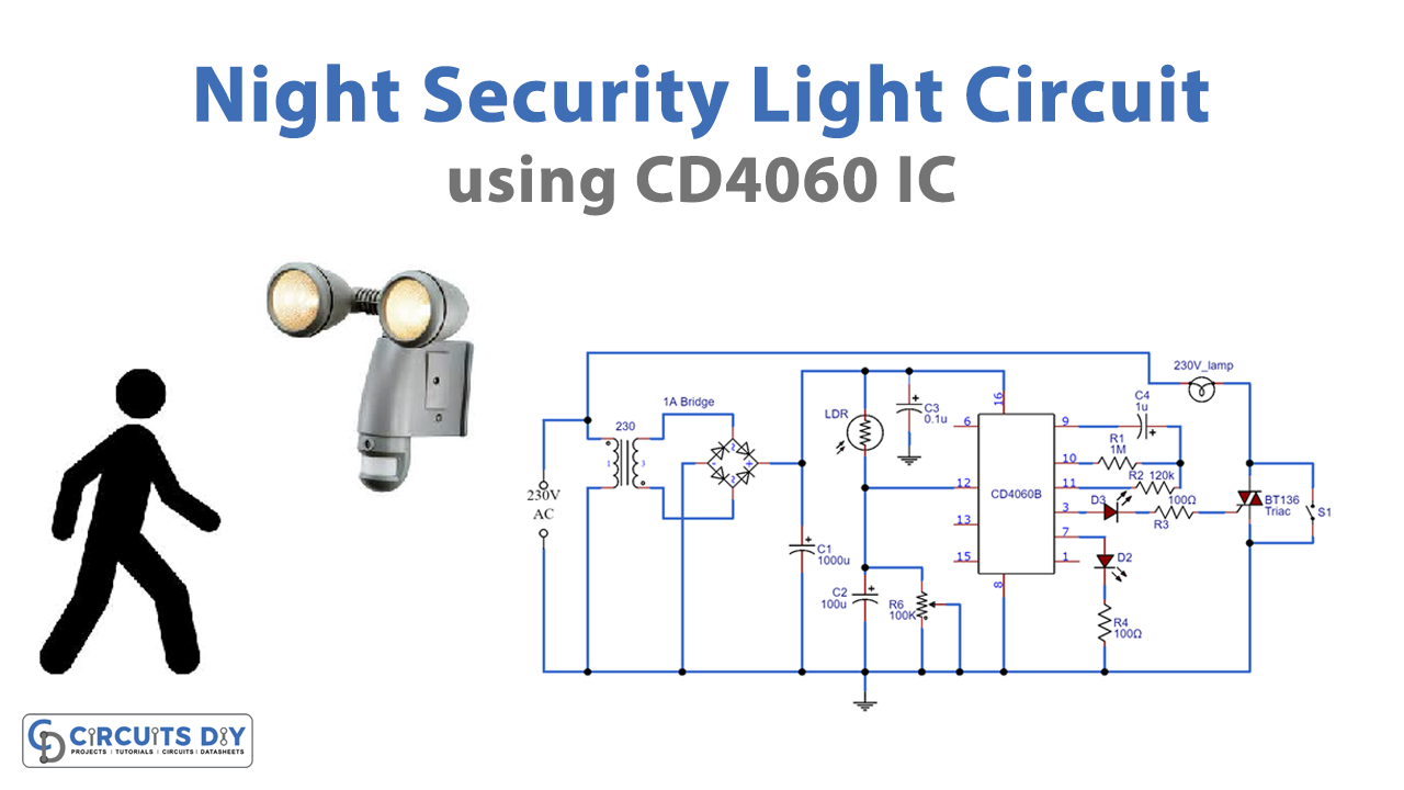
Circuit Diagram
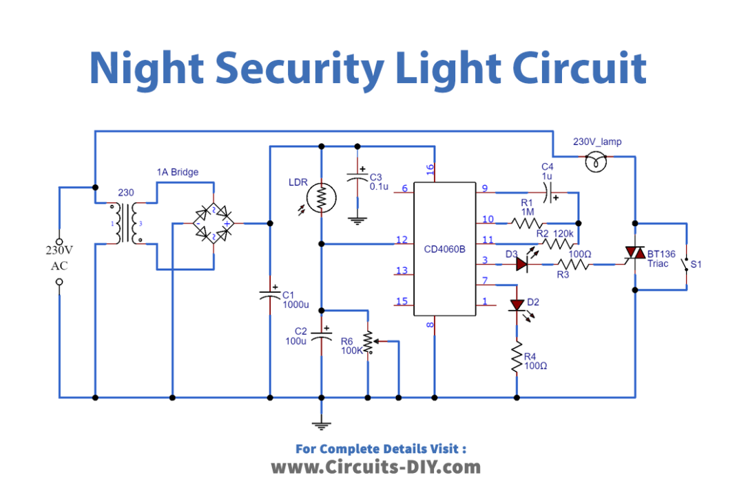
Working Explanation
The CMOS IC is connected to get the required timing. During the day when the resistance is low, pin 12 of IC is high. Therefore, there would be no oscillation. At night pin 12 becomes low and oscillation starts, specified by LED D3. R1, R2, and C4 work as timing components that select the output at pin 3 of IC to get high after 8 hours. This output from pin 3 drives the trial to the switch that drives the load, which is a lamp.
Application and Uses
- The main application is used for security purposes at night