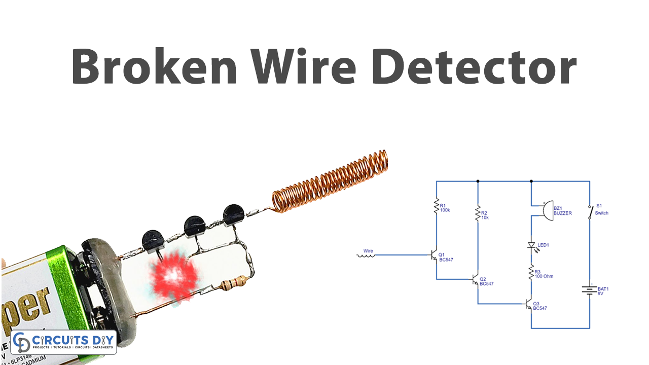
Introduction
Sometimes it happens that after making any device or circuit it would not work properly. So, the first thing a person can do is to check the wire’s connectivity. The students of electronics mostly used multimeters for that purpose to check the continuity. But, many times, the circuits are very complicated. Thus, it is not easy to check them manually. Moreover, it is almost impossible to check commercial or industrial devices or circuitry by this method. Hence, we need a proper circuit that can handle this issue. Thus, detectors are used for this purpose. So, to understand this, in this tutorial, we are going to ” Simple Broken Wire Detector “
Hardware Required
| S.no | Component | Value | Qty |
|---|---|---|---|
| 1. | NPN Transistor | BC547 | 3 |
| 2. | Buzzer | – | 1 |
| 3. | LED | – | 1 |
| 4. | Battery | 9V | – |
| 5. | Resistor | 100KΩ, 10KΩ, 100Ω | 1, 1, 1 |
| 6. | Switch | – | 1 |
Circuit Diagram
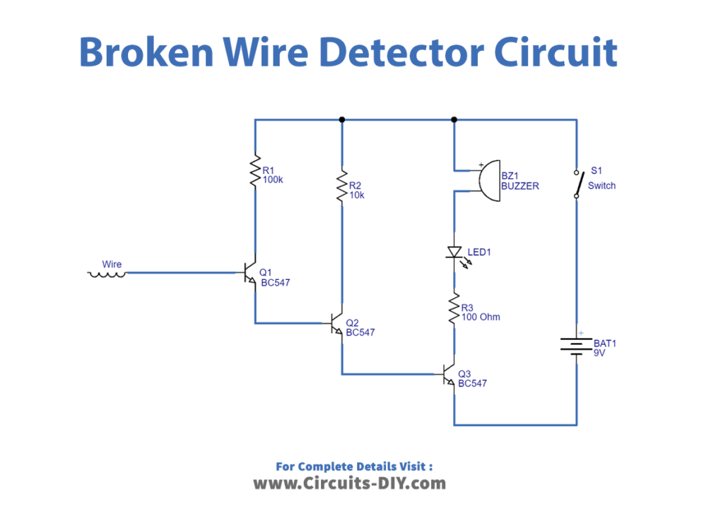
Working Explanation
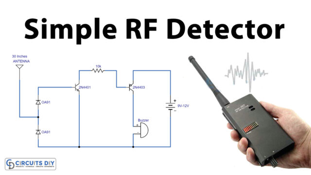
This whole Simple Broken Wire Detector is biased with a 9V battery. The short wire working as an antenna is connected with the base of the transistor Q1 and the same transistor gets biased through resistor R1. Q2 transistor is biased through R2 and Q3 is biased by R3 which drives the load. If there are any broken wires, the wire which is used as an antenna will detect that. The signal is then amplified by three transistors which make the buzzer beep and LED glow.
Application and Uses
This circuit is basically for every commercial, industrial, or any electronic circuitry that requires to detect needs to check the broken wires.