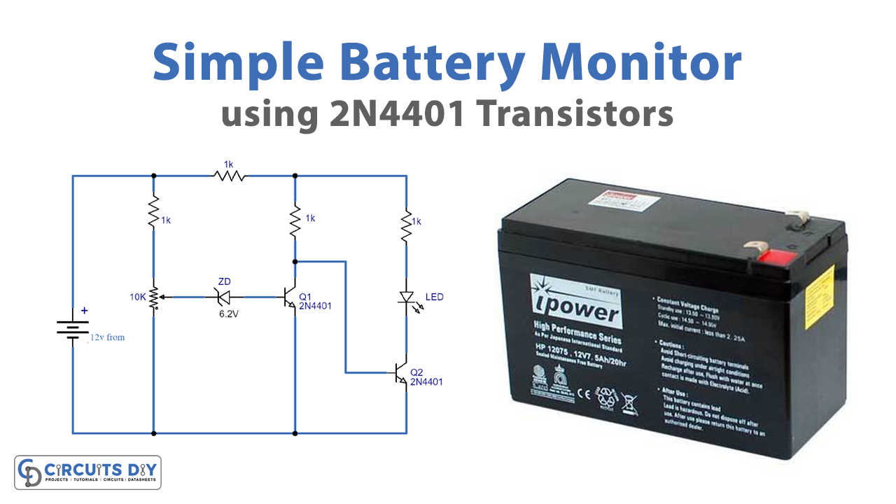
All rechargeable batteries have their own charging and discharging levels, they are likely to experience harm if the voltage of the battery reaches that level. Here is a basic circuit battery voltage monitor used to track it to show the battery status.
The circuit will control the voltage of 12 and 9 V batteries and will signal when the battery level exceeds the predetermined value by triggering an LED. When you are using it on a 12V cell, for example, so you want the circuit to say whether the voltage level will approach 9 V, 10 V, or 11 V. You then need to configure this using the 10 K variable resistor that is used in the circuit
Hardware Components
The following components are required to make Battery Monitor Circuit
| S.no | Component | Value | Qty |
|---|---|---|---|
| 1. | Resistors | 1K | 4 |
| 2. | LED | – | 1 |
| 3. | Zener diode | 6.2v | 1 |
| 4. | Transistor | 2N4401 | 2 |
| 5. | Potentiometer | 10K | 1 |
| 6. | battery | 12v | 1 |
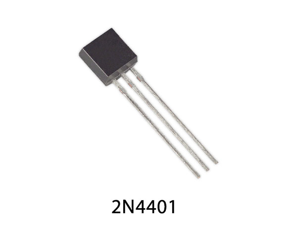
2N4401 Pinout

For a detailed description of pinout, dimension features, and specifications download the datasheet of 2N4401
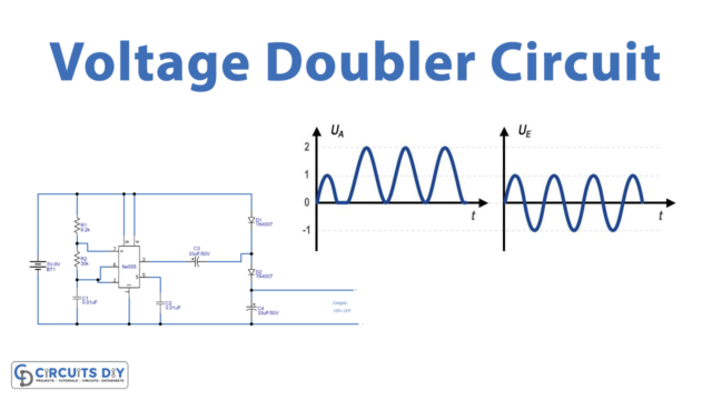
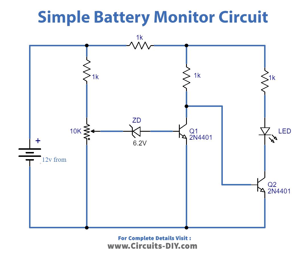
Battery Monitor Circuit
Working Explanation
The battery monitor circuit only requires two transistors and several resistors. All the transistors act as switches, the transistor Q 1 will be in ON condition with a completely charged battery, and Q2 will be in of. As the battery voltage is exceeded by the 10 K variable resistor at the preset value then the transistor Q 1 is the OFF switch and Q 2 turns ON and triggers the Lead. The circuit will also be used to track the 6 V or 4.5 V batteries by using a 3.3 V/ 1N746 or 4.3 V/ 1N749 Zener diode.
Applications and Uses
- For various batteries such as car batteries, other lead-acid batteries, NiCd and NiMH batteries, etc., this battery monitor circuit can be used.