Often we see Light Emitting diodes are used in every other electronic circuit. Especially, it is used regularly at the output side for the indication. So, we thought why not make a very fun project of LED chasers, which is greatly used in today’s world. For example, you may have seen this circuit at parties, weddings, or restaurants. So, in this article w will make the LED chaser circuit. The circuit uses very few components including the IC CD4017.
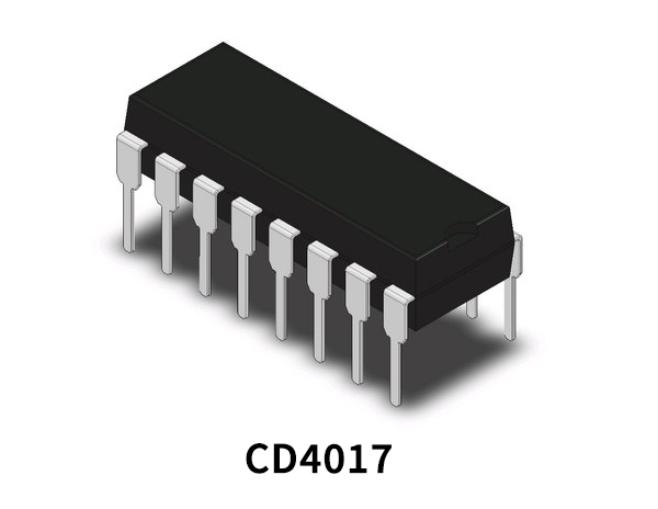
IC CD4017 is a decoder IC having ten output pins. The IC can count from 0 to 9 and that’s why we will use 10 output LEDs to make our circuit. Each output of this IC includes a buffer and can easily drive an LED. This buffer gate is inside the integrated circuit. Therefore no external circuits are needed for that purpose. To make this chaser circuit with this IC, give input power to pin 16 and ground pin number 8. Connect the output stage to the output pins, which are from pin 1 to 7 and pin 9 to 11.
Hardware Components
| S.no | Component | Value | Qty |
|---|---|---|---|
| 1. | Breadboard | – | 1 |
| 2. | Resistor | 470-ohm, 330-ohm | 1 |
| 3. | LED | – | 11 |
| 4. | Battery | 9v | 1 |
| 5. | IC | CD4017 | 1 |
| 6. | Multicolor LED | – | 1 |
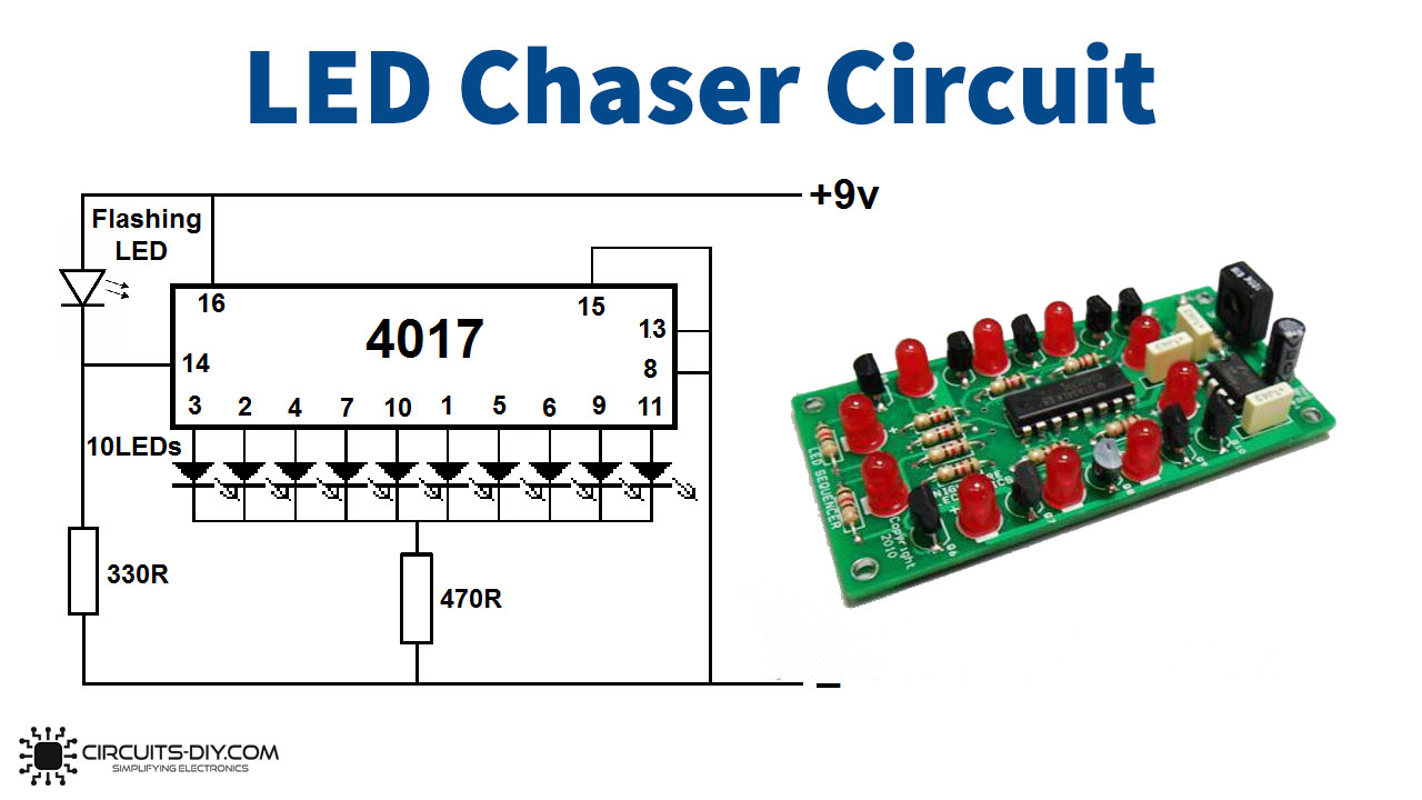
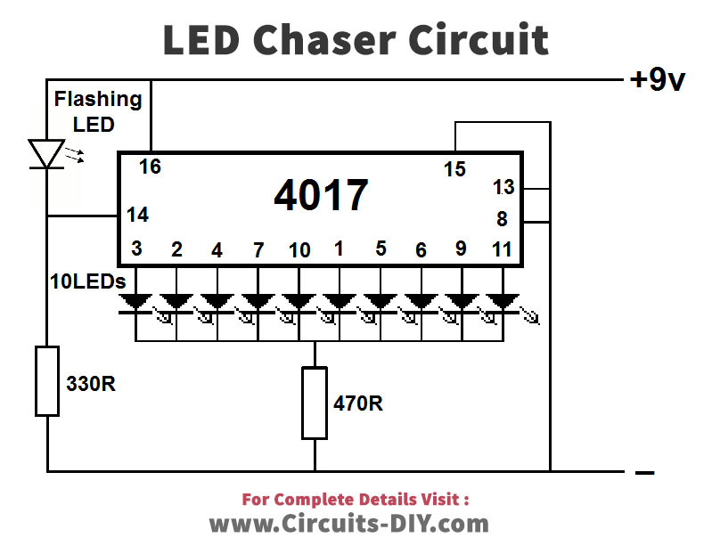
Circuit Diagram
Working Explanation
To make the connections of the LED chaser circuit, understand the configuration of an IC. CD4017 is a CMOS counter IC, having 10 output pins, from pin 1 to pin 7 and pin 9 to pin 11. Pin 16 is for the applied voltage from 3V to 15V, while pin 8 is for ground. Pin 13 is for the clock, when there’s logic zero, the clock gets enabled and the counter increases one count for every clock pulse. When there’s logic one, the clock input gets stopped, and the counter does nothing when the pulse arrives. This circuit also works in the same way. Flashing LED is used for triggering.
Applications
- In LED strips circuits.
- FOr decoration purposes.
- In counter circuits, etc.