Introduction
If you have an eye side-related issue, the word LASER is what you have heard either from your doctor or from the people around who suggest you every time go for it. If you work in any mechanical industry, you must have seen the LASER applications in cutting, drilling machines, etc. If you’re a doctor or a dentist, then you have surely known how LASER effectively cures some diseases. Hence, the use of LASER is in so many industries. And, if you’re an engineer, then you must have known its applications. But, if you’re an electronic engineer or a student, then it’s your ability to discover how to drive that laser diode. In this tutorial, we have come up with a “Single Supply Laser Driver Amplifier Circuit”
Hardware Components
The following components are required to make Laser Driver Amplifier Circuit
| S.no | Component | Value | Qty |
|---|---|---|---|
| 1. | Zener diode | LM385BZ | 1 |
| 2. | Transistor | FMMT619 | 1 |
| 3. | Laser Diode | – | 1 |
| 4. | Potentiometer | 10K | 1 |
| 5. | SMD Capacitor | 11uF, 39pF | 1,1, |
| 6. | SMD Resistor | 1Ω, 10Ω, 10K,100Ω, 330Ω | 2,1,1,1,1 |
| 7. | Connector | 2-Pin | 2 |
| 8. | IC | LT1800 | 1 |
LT1800 Pinout
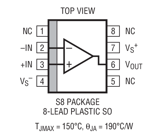
For a detailed description of pinout, dimension features, and specifications download the datasheet of LT1800
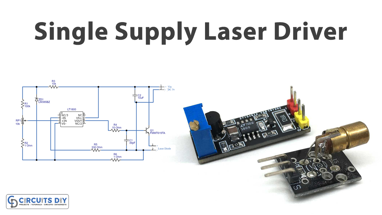
Laser Driver Amplifier Circuit
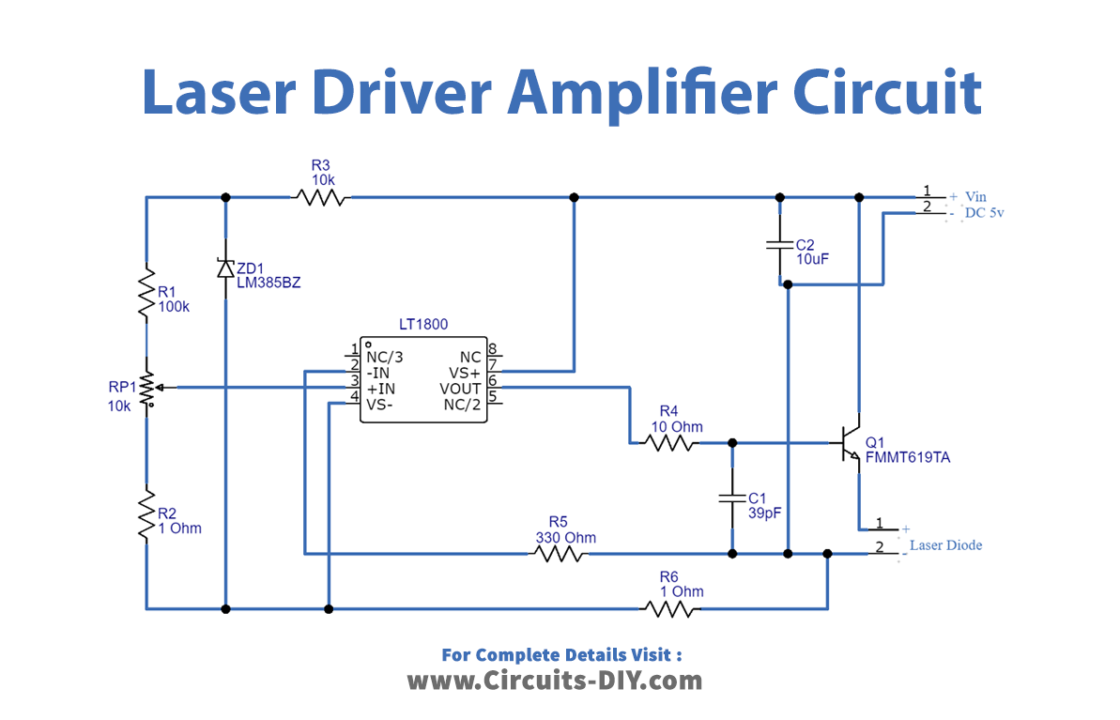
Working Explanation
This Single Supply Laser Driver circuit is using the LT1800 IC and has 8 pins. Pin 7 is connected with the positive supply, while pin 4 is for the ground. Inverting pin of this amplifier IC is connected to the output pin with the help of capacitor C1. A potentiometer is wired with the non-inverting pin of the integrated circuit which helps to change the intensity of LASER at the output side. Output is taken at pin 6 of an Ic and then applied to the base of the transistor which amplifies the signal and drives the LASER diode.
Application and Uses
- In medical applications.
- In industrial applications.
- Also, in some military applications, etc