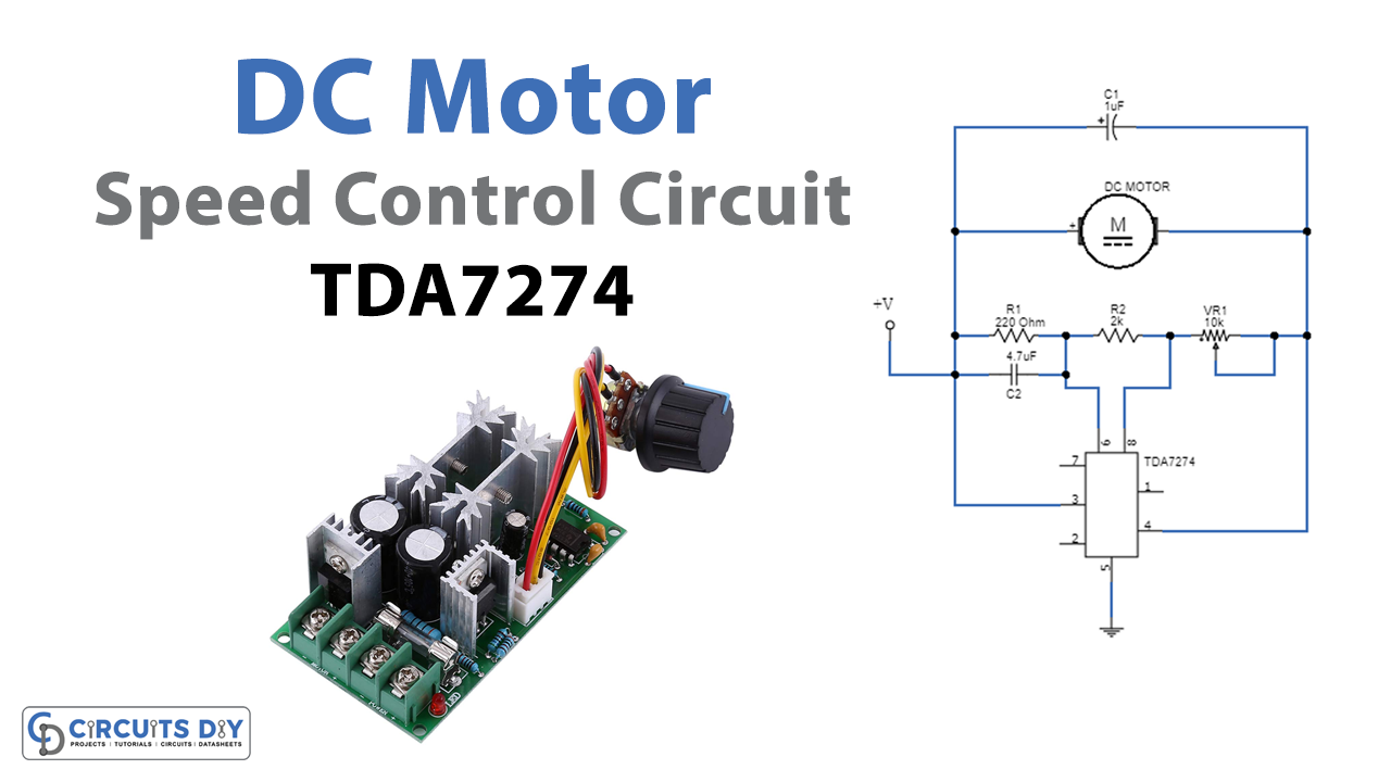
Unlike AC motors, DC motors are very easy to use because of the ease with which their speed can be changed. So, how is this achieved in practice? Speed control of a DC motor is required to keep a motor running at a constant speed. This is because the motor’s load torque varies due to the load itself, as well as other factors such as temperature, humidity, and changes over time. Simply driving the motor with a constant voltage will result in its speed fluctuating with changes in load. This low-voltage DC motor speed control circuit is designed by using TDA 7274 IC and some other easily available components.
Hardware Required
| S.no | Component | Value | Qty |
|---|---|---|---|
| 1. | IC | TDA7274 | 1 |
| 2. | DC Motor | – | 1 |
| 3. | Resistor | 2KΩ,220Ω | 1,1 |
| 4. | Variable Resistor | 10KΩ | 1 |
| 5. | Capacitor | 1uF,4.7uF | 1,1 |
| 6. | Connecting Wires | – | – |
| 7. | Battery | 6V | 1 |
TDA7274 Pinout

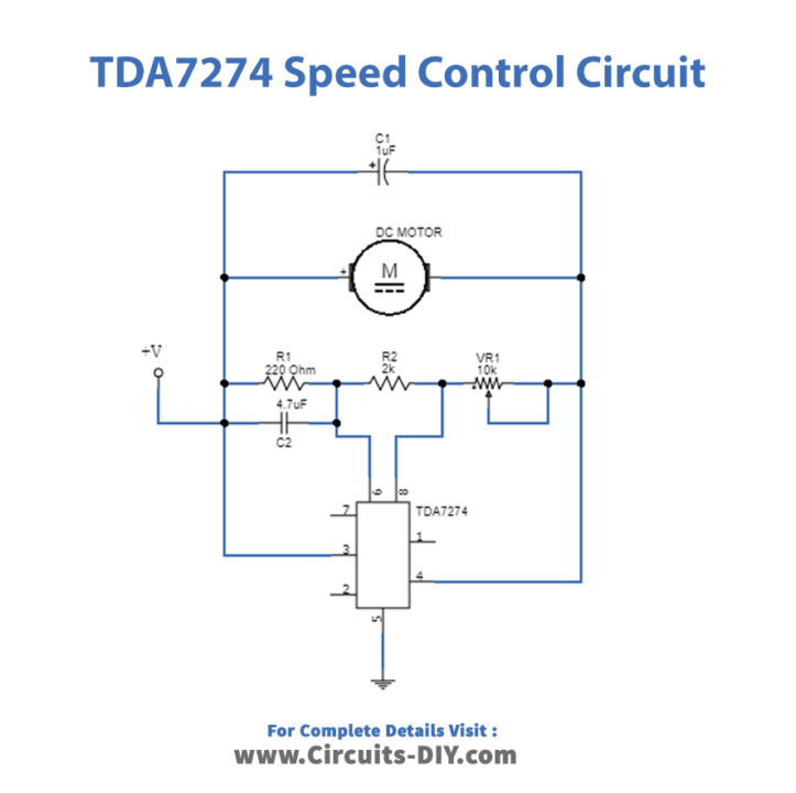
Circuit Diagram
Construction and Working
As we can see from the circuit, the motor is connected between pin3 and pin4 of IC TDA 7274. Here resistors R1, R2, and VR1 are connected in series with each other and then connected with pin 6, and pin 8 of IC 7274. The circuit can be assembled on a Perf board. And power supply can be anything between 1.8V to 6V and it must be selected according to the rating s of the motor. Now we can control the speed of the DC motor by varying VR1. The maximum output current capacity of this circuit is 700mA.
Applications
This circuit is designed for DC motor speed control in microcassettes, radio cassettes, and low-voltage applications.