In this tutorial, we will make an “AC Power Interruption Counter Circuit”. AC currents can be interrupted at a natural current zero, which is primarily determined by the circuit alone. And practically unaffected by the presence of the interruption device. Alternately, AC currents can be interrupted at forced current-zeros, which are imposed by the action of the interruption device. Here the simple and easy circuit is designed, to count the occurrence of power supply interruption. This circuit will help us to count the AC power interruption, by using seven segment display from 0 to 9 (you can design a two-digit counter by adding another counter stage). It can reset the count when needed. AC Power supply interruption counter based on the number of main interruptions, the user can extend the charging time for lead-acid batteries.
Hardware Required
| S.no | Component | Valur | Qty |
|---|---|---|---|
| 1. | IC | CD4033 | 1 |
| 2. | Seven Segment Display | LTS543 | 1 |
| 3. | IC2 (Opto Coupler Detector) | MCT2E | 1 |
| 4. | Polyester Capacitor | 0.22uf/400V | 1 |
| 5. | Resistor | 33KΩ,390Ω,120Ω,4.7KΩ,2.2KΩ,270Ω | 1,1,1,1,1,1 |
| 6. | Capacitor | 1uf/25V,100uf/63V,10uf/25V | 1,1,1 |
| 7. | Switch | – | 1 |
| 8. | Connecting Wires | – | – |
| 9. | Power Supply | 9V | 1 |
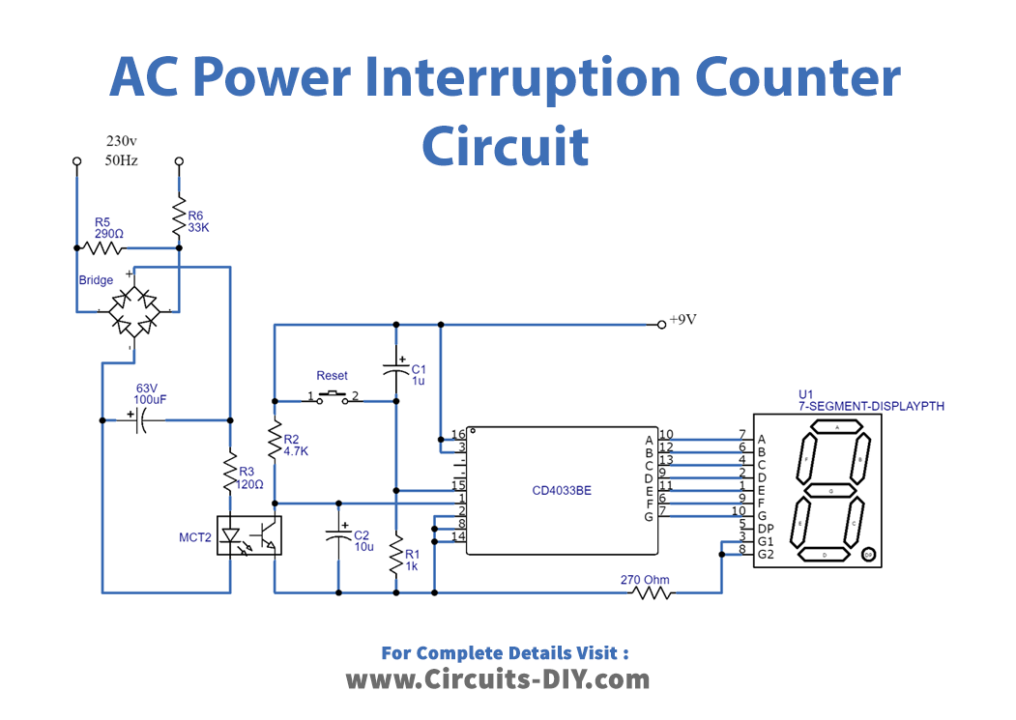
Circuit Diagram
MCT2E Pinout

Working Explanation
This circuit contains three stages, the first one is the AC power input stage, the second stage is opto coupler & johnson decade counter, and the final third stage is the number display. The first stage of this circuit is getting AC power, which needs to be counted on interruption. By using polyester capacitor C1 and bridge rectifier high voltage AC supply bring down to low voltage DC, then IC2 (Opto coupler detector) MCT2E detects the interruption to the AC supply. The event clock is counted by the IC CD4033 (5-stage Johnson decade counter) and drives the seven-segment display LTS543. Now when 9V is applied to the circuit, IC2 is reset by the power-on-reset signal provided by capacitor C3 and resistor R5. And the 7-segment display (DIS1) shows ‘0.’ The 230V AC mains is fed to mains-voltage detection optocoupler IC MCT2E (IC1) via capacitor C1, and resistors R1 and R2.
This is further followed by bridge rectifier BR1, smoothing capacitor C2 and current-limiting resistor R2. Illumination of the LED inside optocoupler IC1 activates its internal phototransistor, and clock input pin 1 of IC2 is pulled down to a low level. IC CD4033 (IC2) is a decade counter/7-segment decoder. Its pin 3 is held high so that the display initially shows ‘0.’ Clock pulses are applied to clock input pin 1, and clock-enable pin 2 is held low to enable the counter. In the seven-segment, common-cathode display DIS1 (LTS543) indicates the mains interruption count. Capacitor C2 provides a small turn-on delay for the display. When mains fails for the first time, clock input pin 1 of IC2 again goes high, and display DIS1 shows ‘1’. When mains resumes, pin 1 of IC2 goes low and DIS1 continues to show ‘1.’ When mains fails for the second time, clock input pin 1 of IC2 goes high, and display DIS1 shows ‘2.’ When mains resumes, pin 1 of IC2 again goes low and DIS1 continues to show ‘2.’ This way, the counter keeps incrementing by ‘1’ on every main interruption. This circuit can count up to nine main interruptions only. This circuit involves the handling of high AC voltage, so take extreme care to avoid lethal shock.
Applications
Can be used in high AC voltage applications.