Introduction
In this Tutorial, we are going to make a “Linear Opto isolator circuit”. An opt isolator, also known as an optocoupler, photocoupler, or optical isolator, is an electronic component that uses light to transfer electrical signals between two isolated circuits. The question may arise in your mind why the Optoisolator/ Opto coupler is important. Because Opto isolators provide a safe method of making high-voltage components and low-voltage devices work in proportion.
Hardware Required
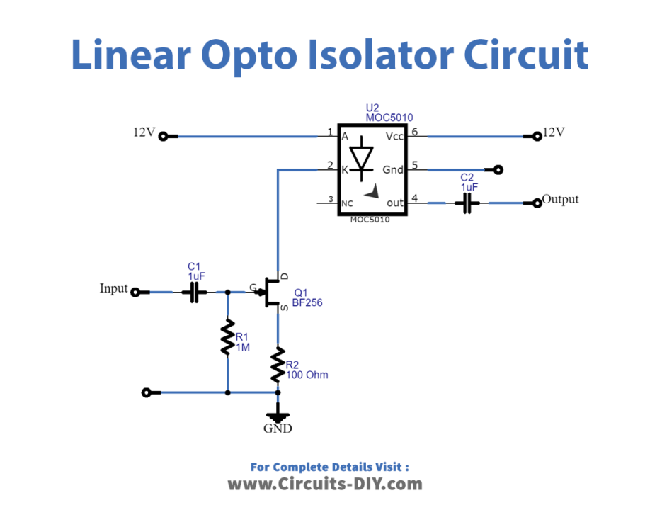
Circuit Diagram
Working Explanation
This Linear Opto isolator circuit uses Optoisolator IC MOC5010. It will change the current that moves at the input into the voltage as a function of the input current ratio. First, the input voltage will be converted to current. As shown in Figure 1, the circuit. It has a gain of 0.75, a maximum input voltage of 2 Vrms, and a frequency band of 118 kHz at -3 dB.
The Mosfet Q1 converts voltage to current, with a Slope of about 3-4 mA per the voltage and an idle current of about 10 mA at the drain-source lead. The Amplifier A transmits resistance at a rate of about 200 mV per mA. As a result, the circuit’s gain will be 0.6 to 0.8. The amplifier’s maximum output impedance is around 200 ohms.
Application Uses
- Microprocessor switching
- Signal Isolation
- High voltage monitoring
- Power control
- Solid state relays, etc