
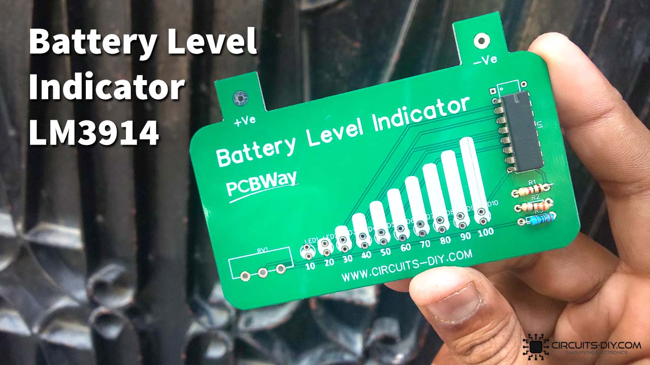
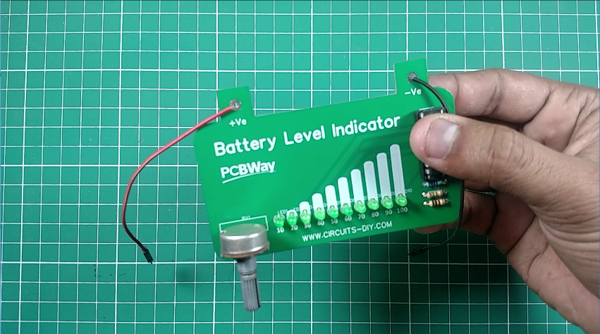
A Battery level indicator (Battery Guage) is an electronic measuring instrument that indicates the immediate voltage level of any DC battery. It is a very common testing circuit, employed in various industries. So today, we are going to build a Battery Level indicator using the LM3914N dot/bar display driver IC.
The LM3914 is an analog-controlled LED driver IC, meaning it can operate (turn on or off) 10 LEDs by an analog input voltage. This IC eliminates the need for programming a microcontroller and also reduces the hardware required to control 10 LEDs. For LM3914, the input voltage can vary from 3V to 18V. The IC has two operating modes DOT mode and BAR mode, also more than one IC can be cascaded to control up to 100 LEDs. Since the LEDs can be controlled without any flickering and perform flawlessly with equal brightness these ICs are commonly used in visual alarms and other metering or monitoring applications.
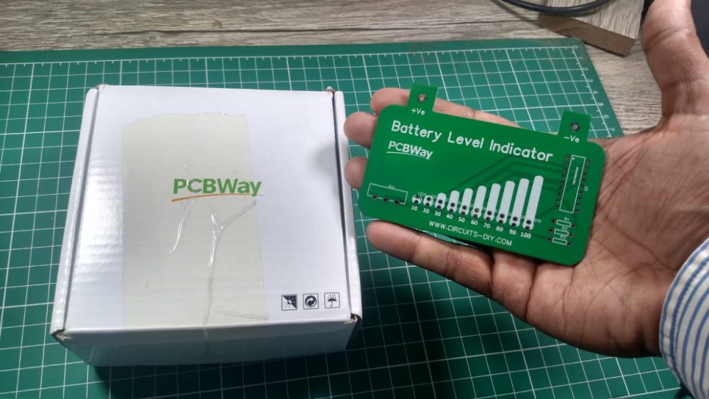
PCBWay commits to meeting the needs of its customers from different industries in terms of quality, delivery, cost-effectiveness, and any other demanding requests. As one of the most experienced PCB manufacturers in China. They pride themselves to be your best business partners as well as good friends in every aspect of your PCB needs.
Hardware Components
The following components are required to make Battery Level Indicator Circuit
| S.no | Component | Value | Qty |
|---|---|---|---|
| 1. | Breadboard | – | 1 |
| 2. | Connecting Wires | – | 1 |
| 3. | Battery | 9v | 1 |
| 4. | IC | LM3914 | 1 |
| 5. | LED | 5mm | 10 |
| 6. | Potentiometer | 10K | 1 |
| 7. | Resistors | 1K, 4.7K, 18K | 1,1,1 |
LM3914 Pinout
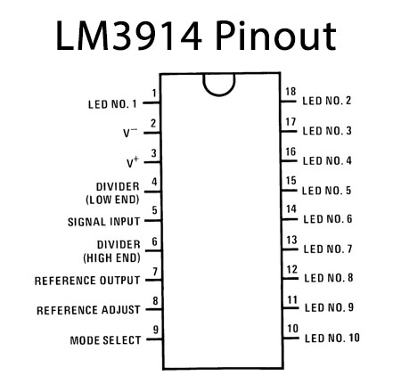
For a detailed description of pinout, dimension features, and specifications download the datasheet of LM3914
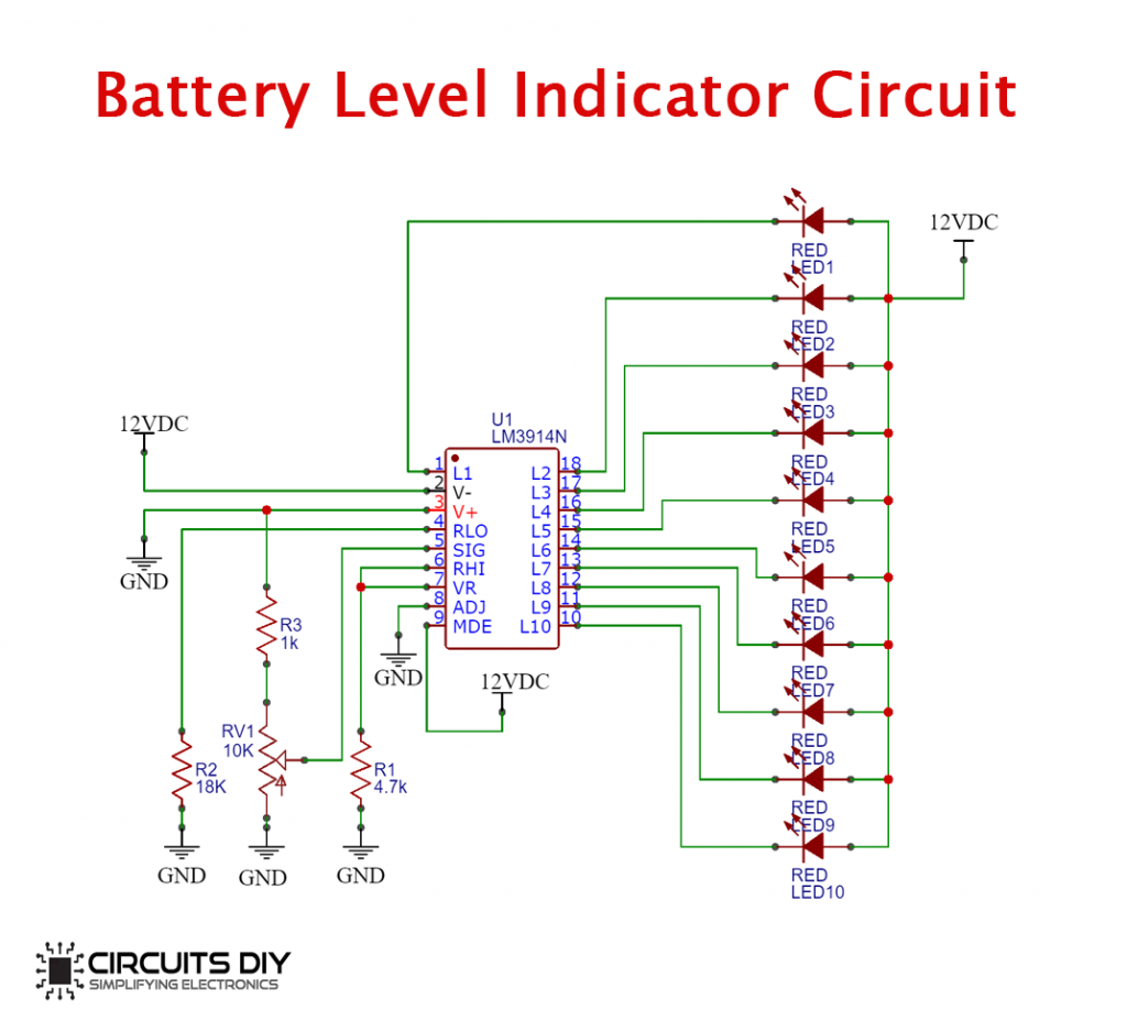
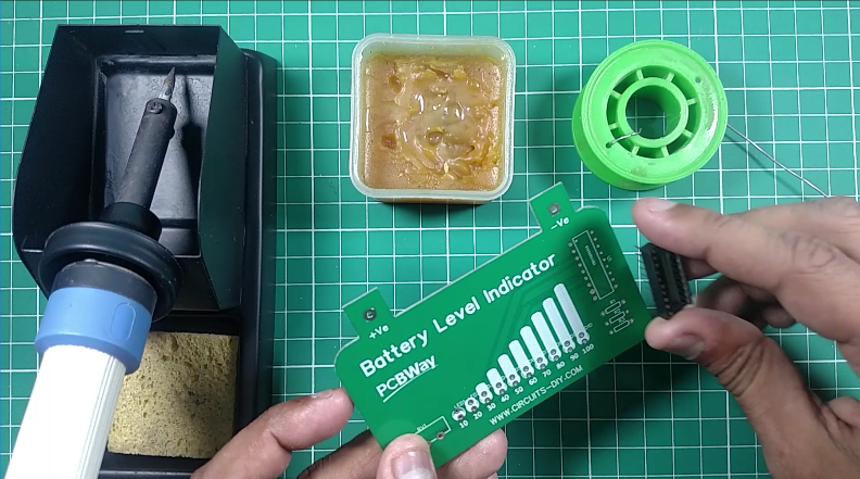
Battery Level Indicator Circuit
Steps
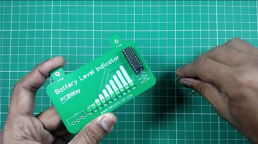
1) Step1: Solder IC with Base
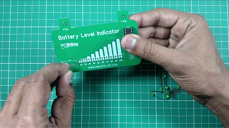
2) Step2: Solder LED’s
3) Step 3: Solder Resistors
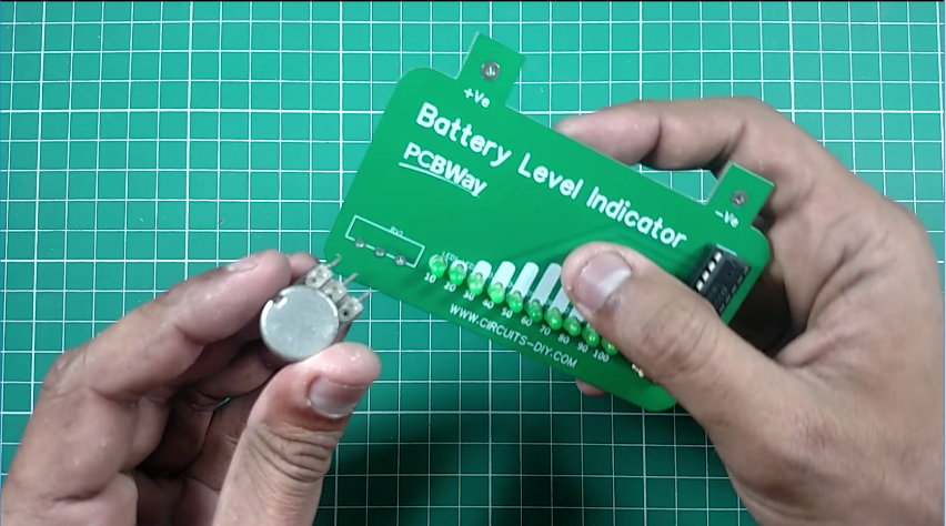
4) Step 4: Solder Variable Resistor
5) Step 5: Solder Battery Terminals
Working Explanation
This circuit is designed to monitor 10V to 15V DC. The circuit will work even if the battery voltage is 3V. In this circuit LED (D1-D10) displays the capacity of the battery. Here, the 1K resistor & the 10K Potentiometer form a potential divider circuit, where the POT is used to calibrate the Input signal. There is no need for any external power supply to this circuit as the circuit functions as measuring equipment for any DC battery connected to it.
The IC can operate in two different modes, one is the dot mode and the other is bar mode. In Dot mode, the MODE pin (pin 9) is open by using a toggle switch, in this mode, only one LED will turn on depending on the input voltage. In Bar mode, the mode pin (pin 9) connects to the V+ pin and the LED will turn on or turn off sequentially based on the input voltage.
Applications
- Battery level indicators can be used with home inverters & any Battery operated device to provide an indication of battery status.
Related posts:
 Heartbeat Sensor Circuit Using LM358 - Electronics Projects
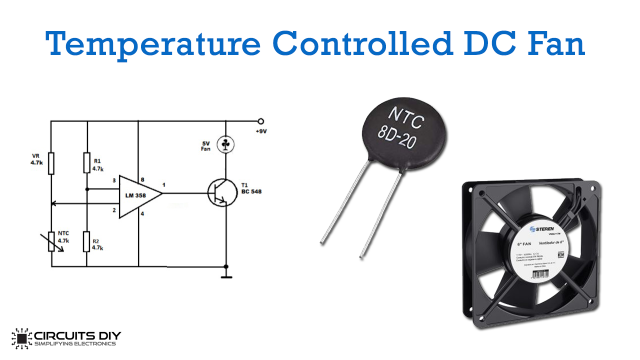 Temperature Controlled DC Fan using Thermistor
 Top 10 Easy Electronics Projects using NE555 Timer IC for Beginners
 Simple Water Level Indicator - Electronics Projects
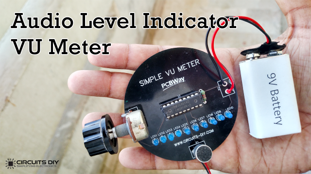 How to make Audio Level Indicator - VU meter using LM3914 IC
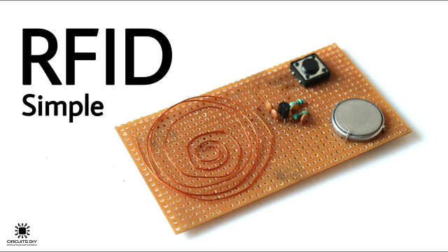 How To Make An RFID Card Reader Without Using An Arduino


2 thoughts on “Battery Level Indicator using LM3914 – Electronics Projects”
Comments are closed.