
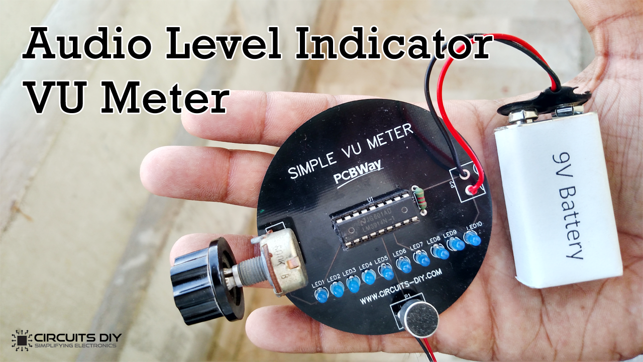
An Audio Level Indicator (VU meter) or volume unit meter, are electronic devices that display the intensity of any Input audio signal, usually in musical pieces of equipment (Drum sets, mic, electric guitars, amps, speakers, etc.). More specifically, it helps to visualize analog signals. So, In this project, we are going to design a simple Audio Level Indicator (VU meter) using the LM3914N dot/bar display driver IC.
LM3914 is an analog-controlled LED driver IC, meaning it can control (turn on or off) 10 LEDs by an analog input voltage. This IC eliminates the need for programming a microcontroller and also reduces the hardware required to control 10 LEDs. For LM3914, the input voltage can vary from 3V to 18V. The IC has two operating modes DOT mode and BAR mode, also more than one IC can be cascaded to control up to 100 LEDs. Since the LEDs can be controlled without any flickering and perform flawlessly with equal brightness these ICs are commonly used in visual alarms and other metering or monitoring applications.
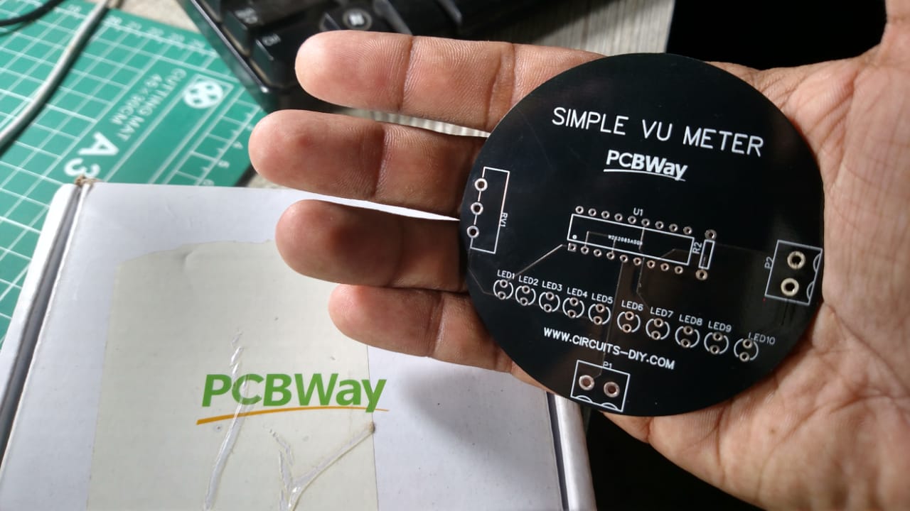
PCBWay commits to meeting the needs of its customers from different industries in terms of quality, delivery, cost-effectiveness, and any other demanding requests. As one of the most experienced PCB manufacturers in China. They pride themselves to be your best business partners as well as good friends in every aspect of your PCB needs.
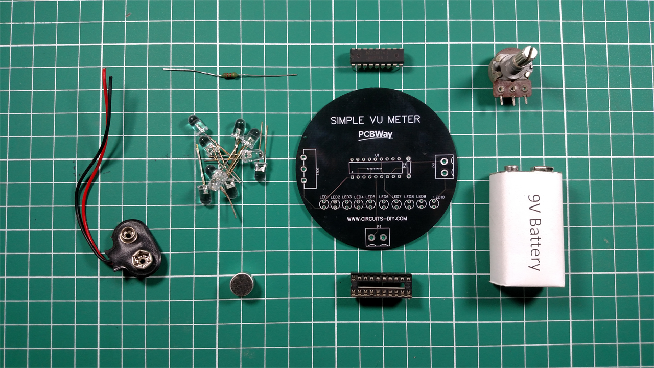
Hardware Components
The following components are required to make Audio Level Indicator Circuit
| S.No | Component | Value | Qty |
|---|---|---|---|
| 1. | IC | LM3914 | 1 |
| 2. | LED | – | 10 |
| 3. | Mic | – | 1 |
| 4. | Audio jack port (Male) | 3.5mm | 1 |
| 5. | Potentiometer | 470K | 1 |
| 6. | Resistors | 1.2K | 1 |
| 7. | DC Power Supply | 12V | 1 |
| 8. | Connecting Wires | – | 1 |
LM3914 Pinout
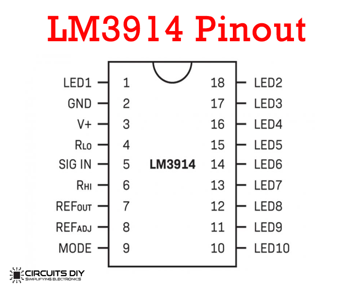
For a detailed description of pinout, dimension features, and specifications download the datasheet of LM3914
Steps
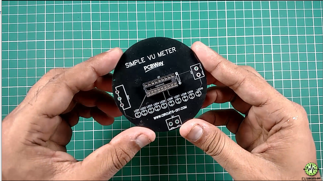
1) Solder IC Base
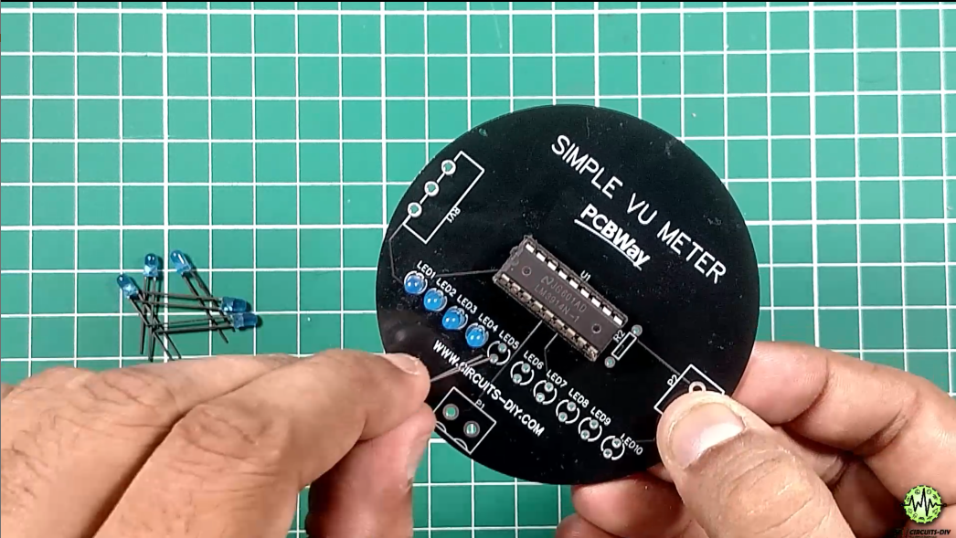
2) Solder All LEDs
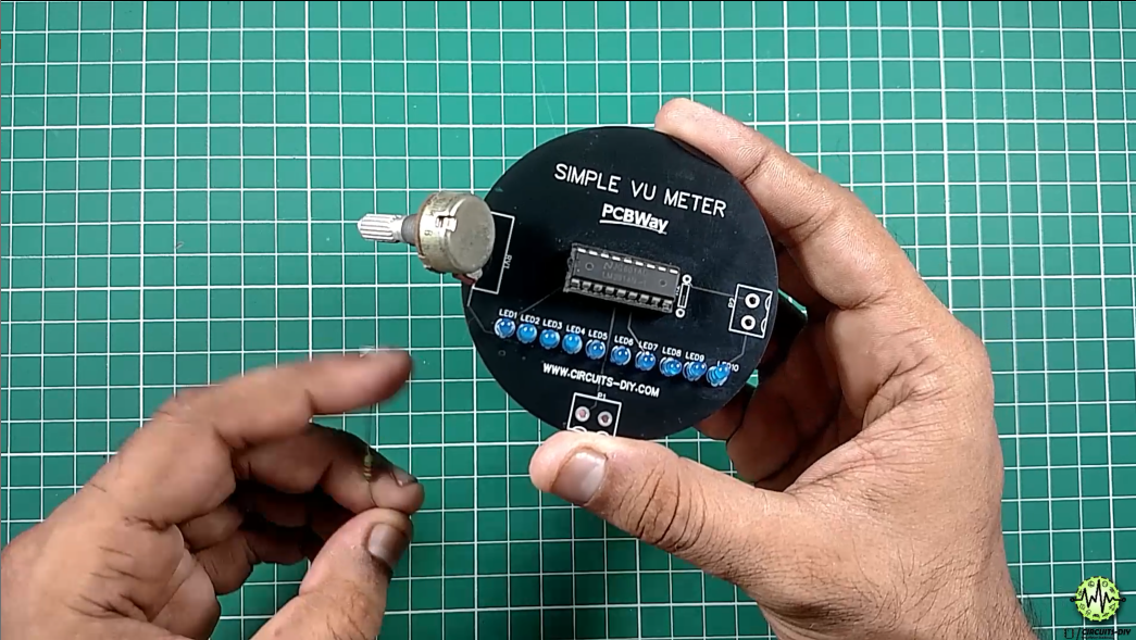
3) Solder Potentiometer & 1.2K Resistor
4) Solder Electret Mic
5) Cut the Signal Wire of the audio cable
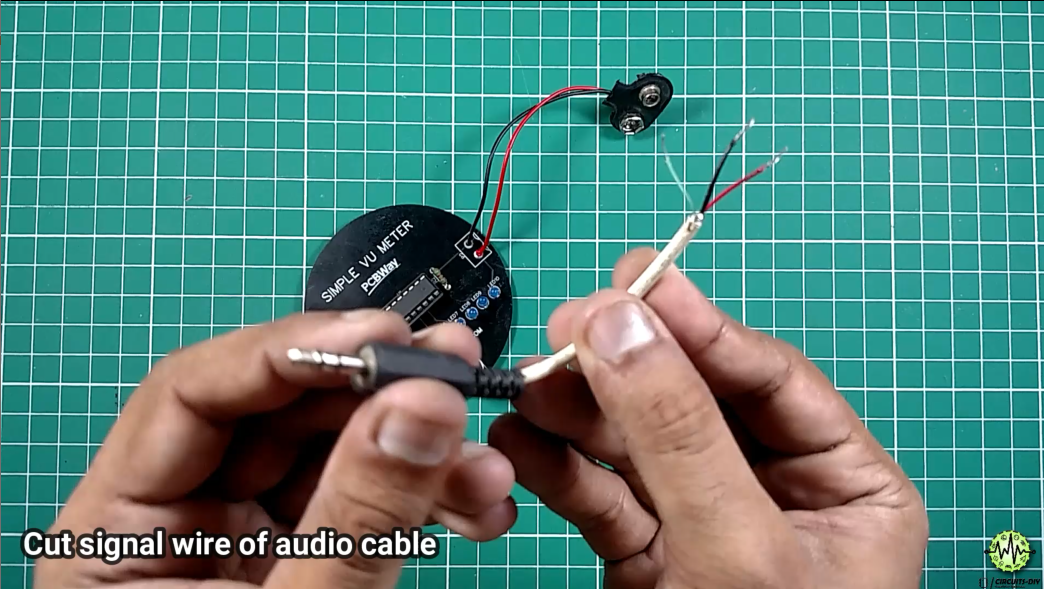
6) Solder Audio Cable in Parallel to Mic

7) Solder Power Connector
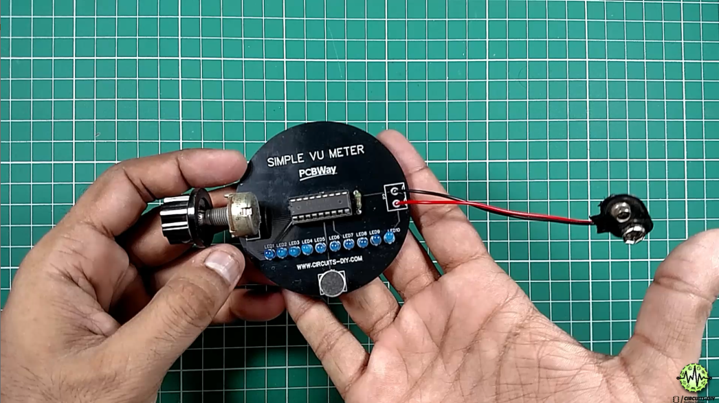
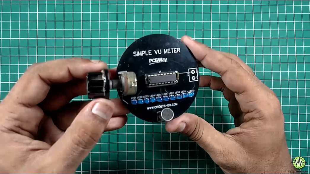
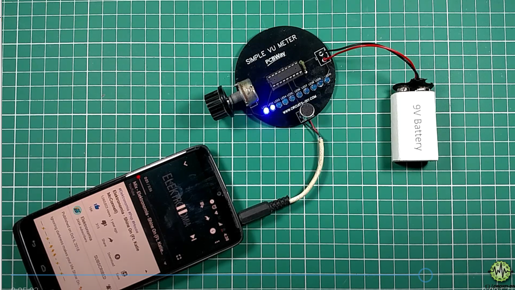
8) Let’s Powerup the Circuit
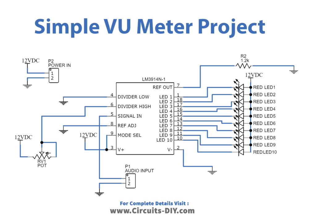
Audio Level Indicator Circuit
Working Explanation
The heart of the circuit is an LM3914N-1 LED driver IC. Firstly, the analog input is coming from P1 Audio Input (Mic/Smartphone). The AC input from the Audio IN enters the SIGNAL pin of the IC. These signals go through the LM3914 integrated comparator. The LM3914 comparator glows the LEDs according to the strength of the given signal. The reference voltage at Pin 7 is set by a resistor (1.2K).
The IC can operate in two different modes, one is the dot mode and the other is bar mode. In Dot mode, the MODE pin (pin 9) is open by using a toggle switch, in this mode, only one LED will turn on depending on the input voltage. In Bar mode, the mode pin (pin 9) connects to the V+ pin and the LED will turn on or turn off sequentially based on the input voltage.
Applications
- It can be reverse-engineered to work as a power level indicator for various energy-storing devices such as batteries and dry cells.
- Also seen in music production & Recording, as a Control/ Testing tool.


Easy to learn and make.. I want to make some edits in the PCB design for my project.. How should I contact PCBway for it?
Perfect here is the link
https://www.pcbway.com/?from=cdiy2020
PCB offer good services, we friends are using this for our projects & we love it
Thanks for sharing your experience
How much the efficiency of this Audio level.
High efficiency this IC LM3914 specially design for this purpose
Great effort dear