An inverter is a simple electronic device that can be used to provide backup power in case of a blackout or grid failure. An easy-to-build inverter can simply do this by supplementing power from a DC battery and translating it into a stable AC signal of the desired voltage level.
Inverters have found their application in every industry, from serving as power backups at home to functioning as key auxiliary power units for complex networking equipment in NOC centers. In today’s article, we are going to go over a step-by-step procedure on how to design an Easy Inverter Circuit using the 2SC1815 NPN transistors.
JLCPCB is the foremost PCB prototype & manufacturing company in china, providing us with the best service we have ever experienced regarding (Quality, Price Service & Time).
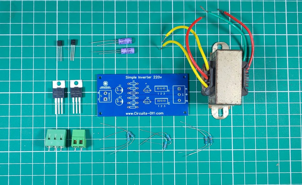
Hardware Components
The following components are required to make the Inverter Circuit
| S.no | Component | Value | Qty |
|---|---|---|---|
| 1. | N – channel MOSFET | IRFZ44N | 2 |
| 2. | Transistor | 2SC1815 | 2 |
| 3. | Transformer | Step-up/12V 3A – 220V | 1 |
| 4. | Inverter Circuit PCB | JLCPCB | 1 |
| 5. | Capacitor | 10uF | 2 |
| 6. | Resistor | 1K, 330 Ohm, 220 Ohm | 2 |
| 7. | Bulb | 220V/LED | 1 |
| 8. | Soldering Iron | 45W – 65W | 1 |
| 9. | Soldering Wire with Flux | – | 1 |
| 10. | DC Battery | 12V | 1 |
| 11. | Battery clips | – | 1 |
| 12. | Jumper Wires | – | As per need |
2SC1815 Pinout

For a detailed description of pinout, dimension features, and specifications download the datasheet of 2SC1815
IRFZ44 Pinout
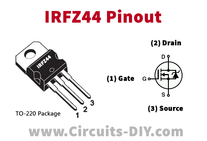
For a detailed description of pinout, dimension features, and specifications download the datasheet of IRFZ44
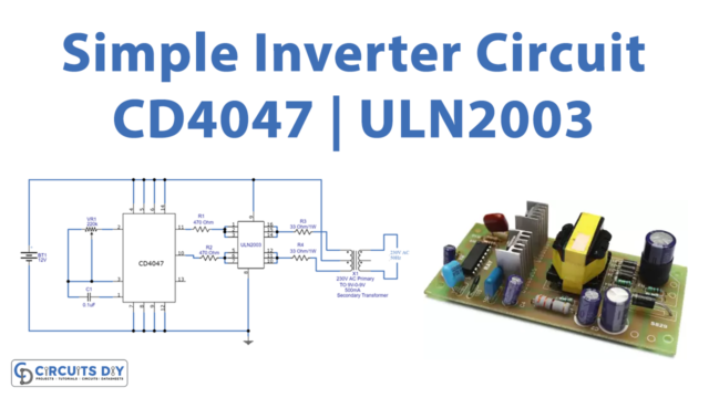
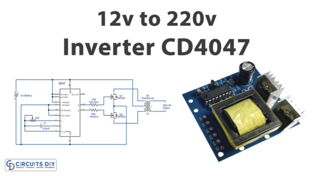
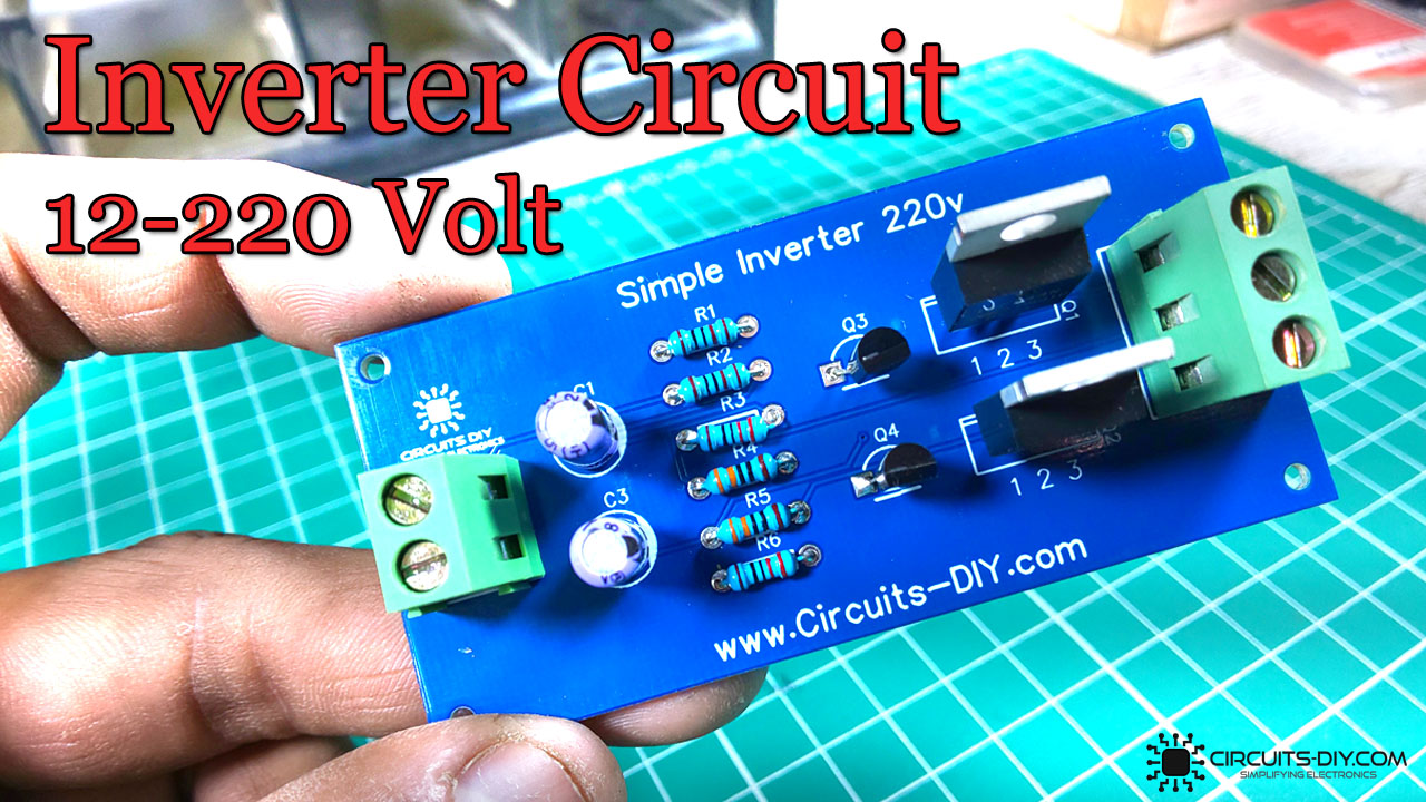
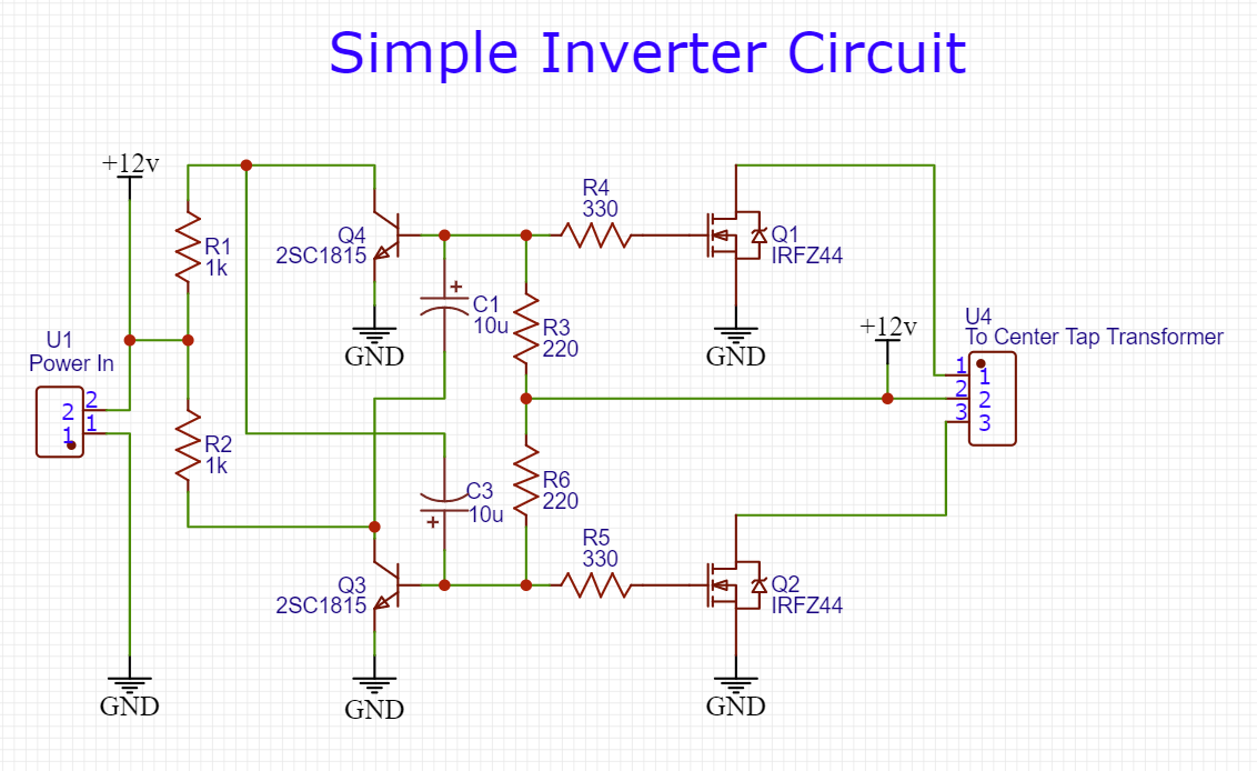
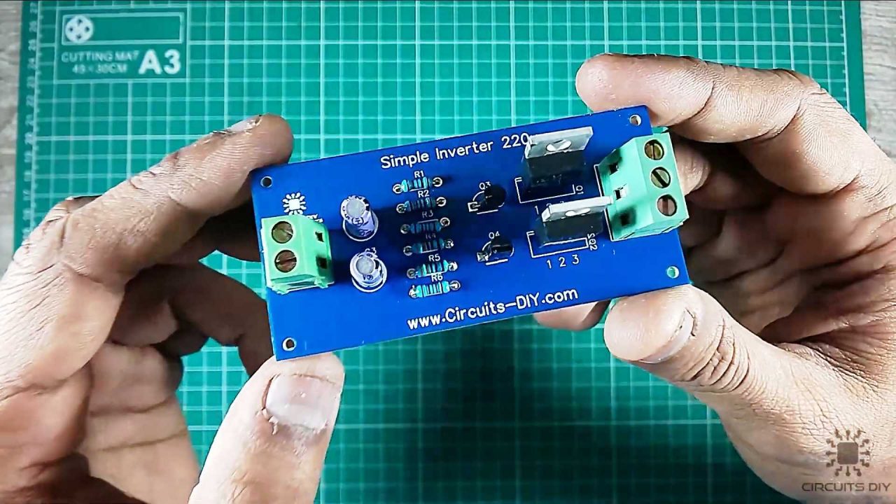
Inverter Circuit
Useful Steps
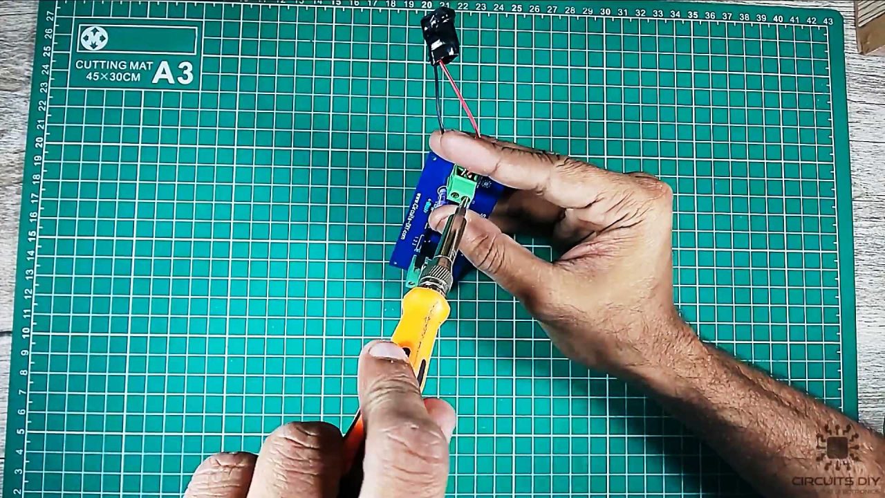
1) First of all, solder all the resistors on the PCB board.

2) After that, Solder the 2SC1815 transistors on the PCB board.
3) Solder the 10uF capacitors on the PCB board.
4) After that, solder the IRFZ44n MOSFETs on the PCB board.
5) Solder the input and output terminal block connectors on the PCB board.
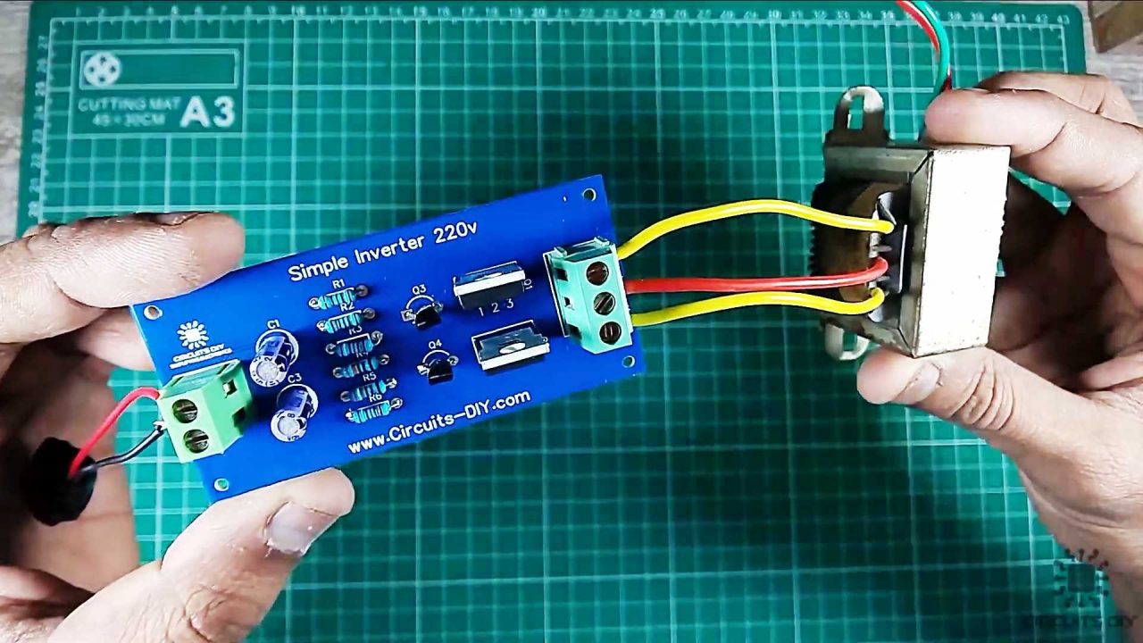
6) Connect the 12V DC power jack with the input terminal block connectors
7) After that, connect the 12V 3A – 220V step-up transformer with the output block terminal of the PCB board.
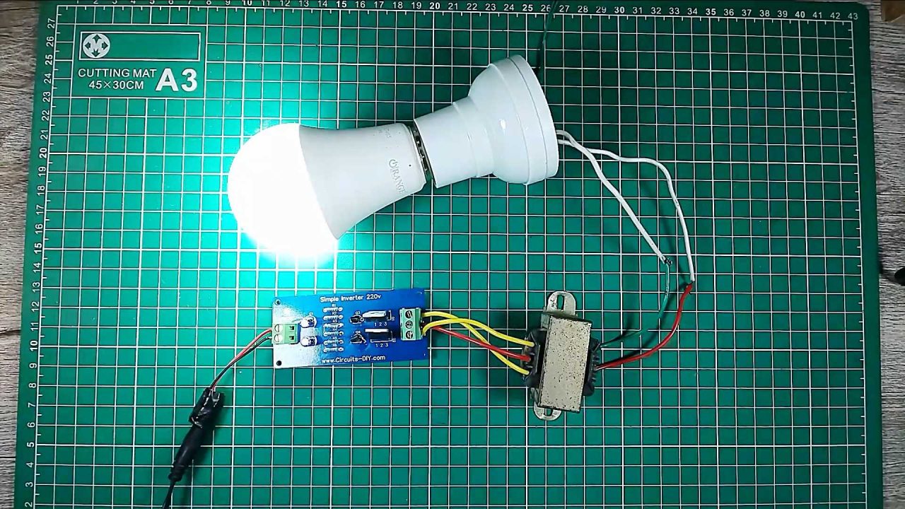
8) Connect a 220V bulb at the transformer secondary. After that, power up and test the circuit using a 12V DC battery.
Working Explanation
The working of this inverter circuit is as follows. Here, we are using two 2SC1815 transistors, configured as a multivibrator circuit running in astable mode, in order to generate a free-running square wave. On powering On the circuit using a 12V DC Battery, a square wave signal is generated by the multivibrator circuit, but, in order to run an AC device without any issues, we require a pure AC sine wave signal from the inverter. This is achieved by chopping off the excess RMS voltage of the astable square wave signal from the multivibrator circuit.
To do this, we feed the square wave output of the multivibrator circuit to two IRFZ44 MOSFETs, this chops up the excess RMS voltage of the square waveform output into a somewhat noisy sine wave signal. The output sine wave signal is then fed to a 12V to 220V step-up transformer, which bumps up the voltage to the desirable AC level of 220V. You can connect an LC configuration in parallel to the output of the transformer to further reduce the noise & improve the waveform of the AC output signal.
Application
- Inverters are commonly used as backup auxiliary power in homes and offices in case of a power failure.