In this tutorial, we are going to make a “12 Volt to 220 Volt Inverter”.
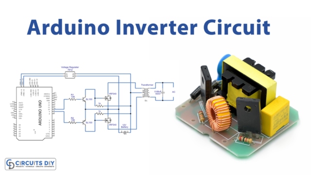
The inverter is an essential component in most PV systems to convert the direct current (DC) PV output into an alternating current (AC) one, allowing the use of AC-powered equipment and grids. It is difficult to provide AC supply from the mains to all components in the system that’s where we needed an inverter. inverter Circuits are very much helpful to produce high voltage using a low voltage DC supply or Battery.
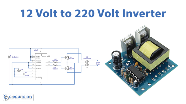
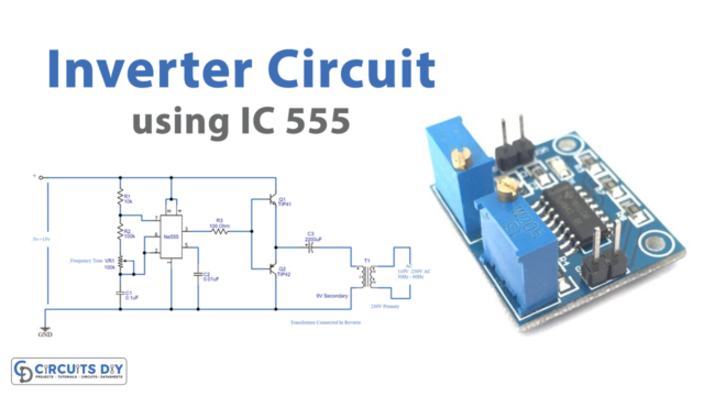
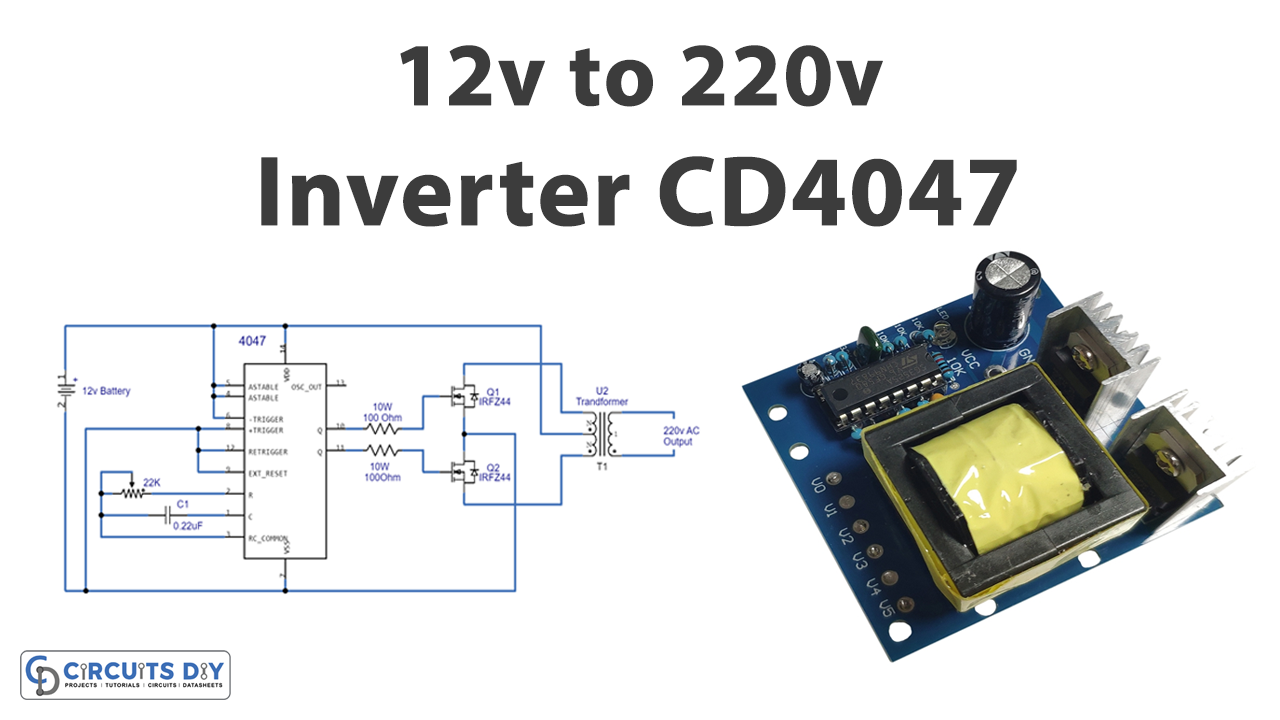
Here we design a 12-volt to 220-volt inverter circuit with a few easily available components. This type of inverter is based on the operation of switching pulse and step-up transformer. Here as a switching pulse oscillating device, we have used the IC CD4047 and n channel power MOSFET IRFZ44n as a switch then 12-0-12V secondary transformer inversely used as a Step-up transformer.
Hardware Components
| S.no | Component | Value | Qty |
|---|---|---|---|
| 1. | IC | CD4047 | 1 |
| 2. | MOSFET | IRFZ44 | 2 |
| 3. | Secondary transformer | 12-0-12V | 1 |
| 4. | Variable Resistor | 22KΩ | 1 |
| 5. | Resistors | 100Ω / 10 watts | 2 |
| 6. | Capacitor | 0.22µF | 1 |
| 7. | Connecting Wires | – | 1 |
| 8. | SLA Battery | 12V | 1 |
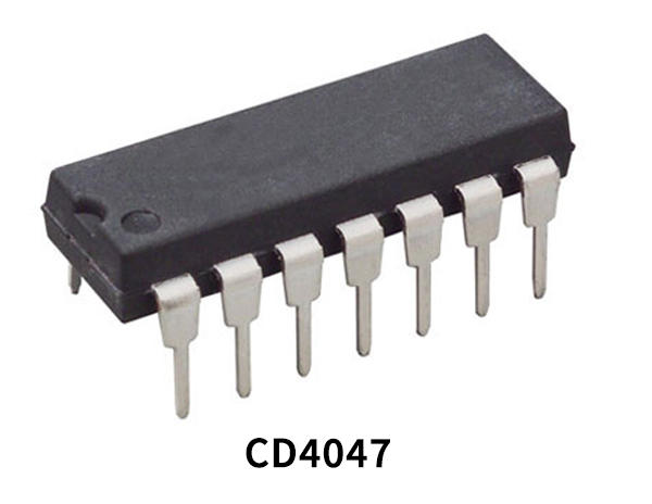
CD4047 Pinout

For a detailed description of pinout, dimension features, and specifications download the datasheet of CD4047
Circuit Diagram
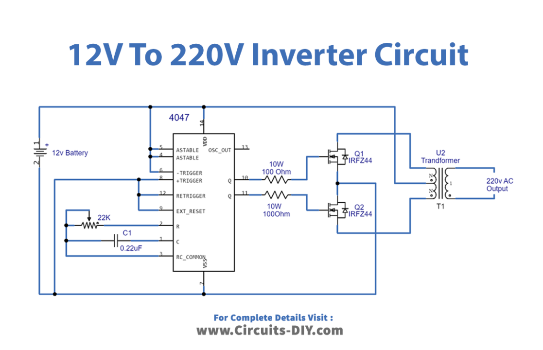
Working Explanation
To construct this simple circuit, we need a switch device and a step-up transformer. As we know due to the mutual inductance high switch frequency pulse reaches the step-up transformer then the output voltage will reach a high value. Here normal 1 amp 12-0-12V transformer is inversely used as a step-up transformer. With the help of variable resistor RV1 and capacitor C1, we configured IC CD 4047 in astable multivibrator mode. We can get a different range of output pulse at Q and Q’ pins by varying the value of the variable resistor and it results in a variation of the output voltage at the transformer.
Now N channel power MOSFETs IRFZ44 Drain pins are connected with the transformer secondary pins and the common pin in the secondary winding is connected with battery positive bias, both MOSFET source pins are connected to the negative bias of the battery, and these MOSFETs are driven by Q and Q’ output from IC CD4047. The secondary winding is forced to induce an alternate magnetic field When the alternate square pulse drives the MOSFET switches then it produces high alternate voltage with this large induced magnetic field (primary) winding of a transformer.
Applications
The inverter may be built as standalone equipment for applications such as solar power, or to work as a backup power supply from batteries that are charged separately.