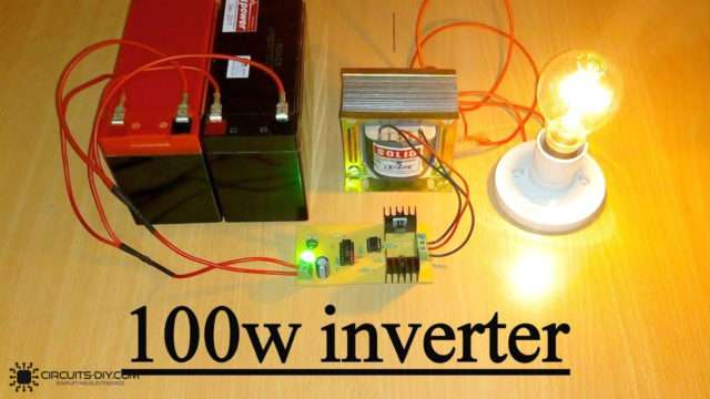
In this tutorial, we are going to make a “100-watt Inverter circuit 12V to 220V using Transistor”.
A power inverter is a power electronic device or circuitry that changes direct current (DC) to alternating current (AC). Let’s say you are the owner of a car, boat, or another vehicle with enough free space and want to be able to watch TV cook, power a laptop onboard, or want to spend some time in the mountains. you’ll be needing a power inverter. They are devices that turn your vehicle battery’s direct current (DC) into alternating current (AC). It increases the DC voltage and changes it to AC, then uses it to power your devices. It can be converted from 12V DC to 220V AC. The maximum output power is about 100 watts.
Hardware Components
The following components are required to make 100 Watt Inverter Circuit
| S.no | Component | Value | Qty |
|---|---|---|---|
| 1. | Transistor | BC557, BD139, 2N3055 | 2, 2, 2 |
| 2. | Diodes | 1N4148, 1N4007 | 4, 2 |
| 3. | Resistor | 10K,47K,100K,150K, (10, 150, 220, 560) ohms | 4, 2, 2, 2, 2, 2, 2, 2 |
| 4. | Ceramic Capacitors | 0.047uF, 0.01uF, 0.1uF, 1uF | 2, 2, 1, 1 |
| 5. | Electrolytic Capacitors | 220uF | 1 |
| 6. | Transformer | – | 1 |
| 7. | Heat sink | – | 1 |
| 8. | PCB | – | 1 |
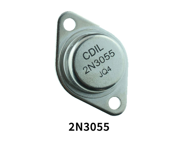
2N3055 Pinout
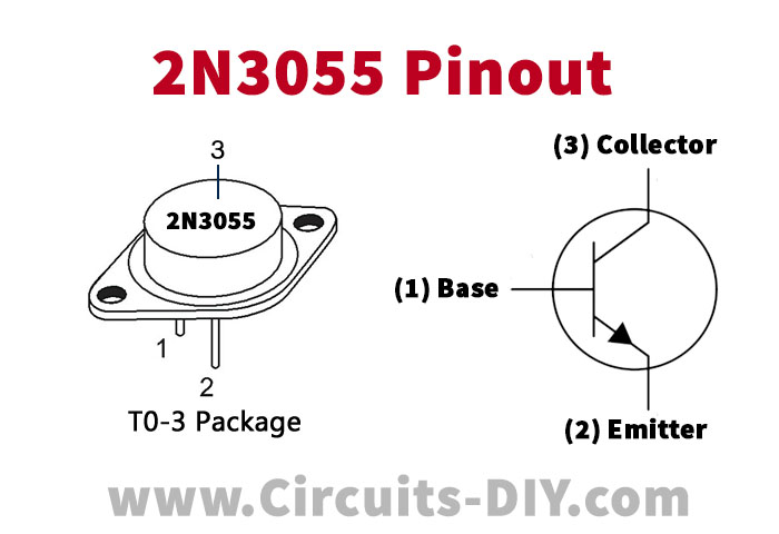
For a detailed description of pinout, dimension features, and specifications download the datasheet of 2N3055
BD139 Pinout
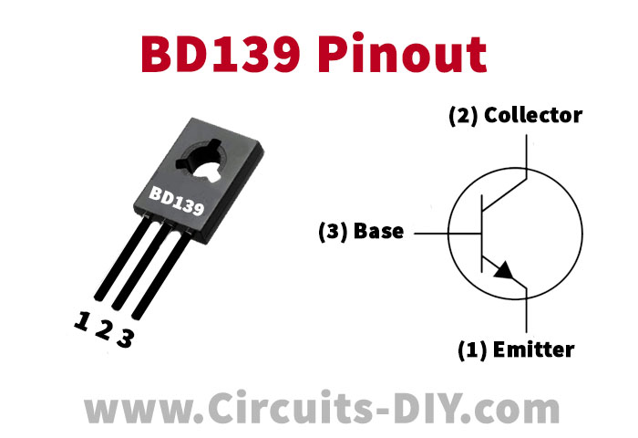
For a detailed description of pinout, dimension features, and specifications download the datasheet of BD139
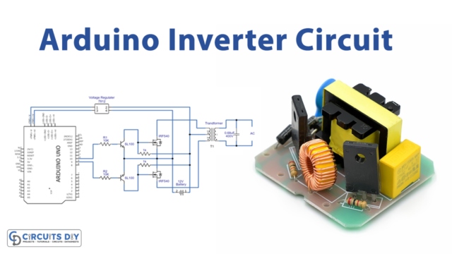
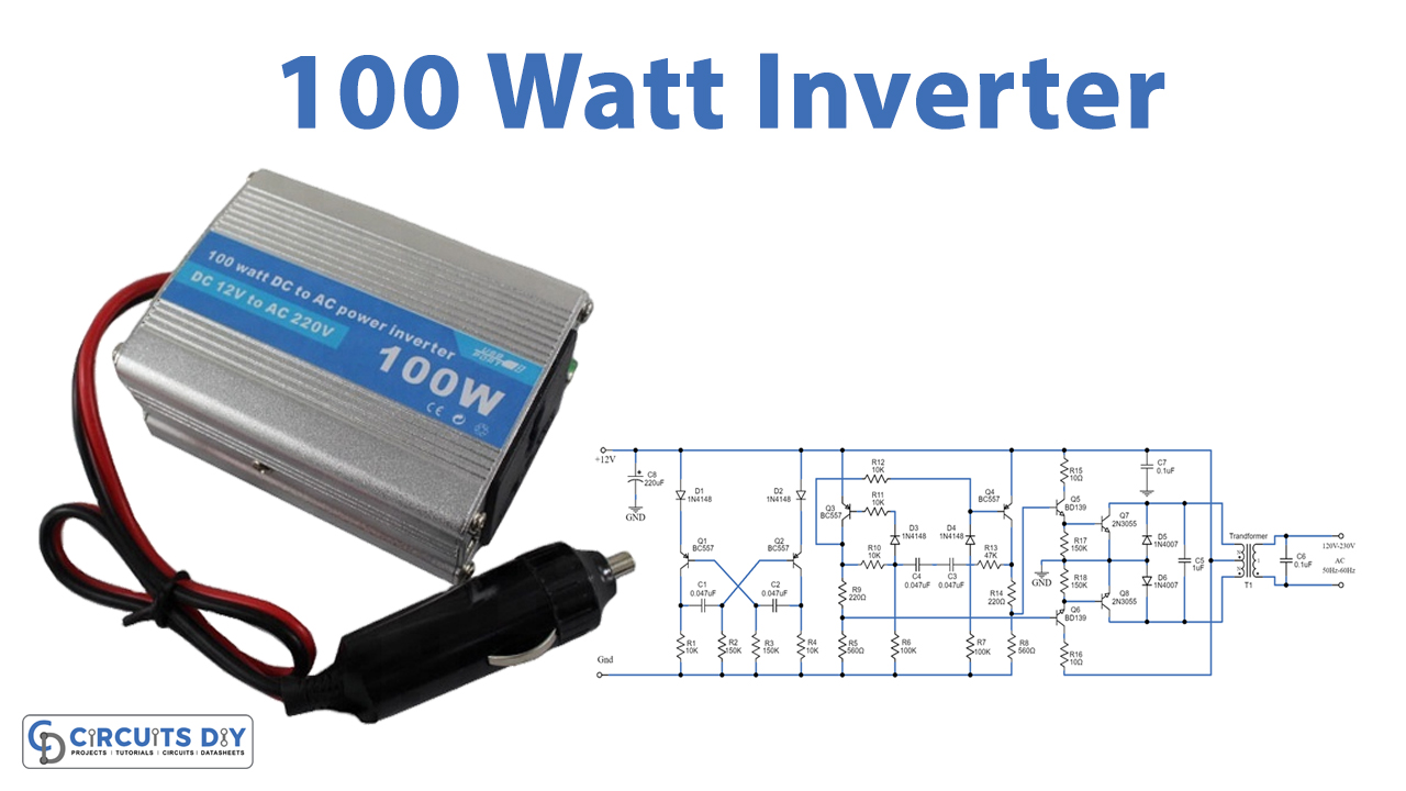
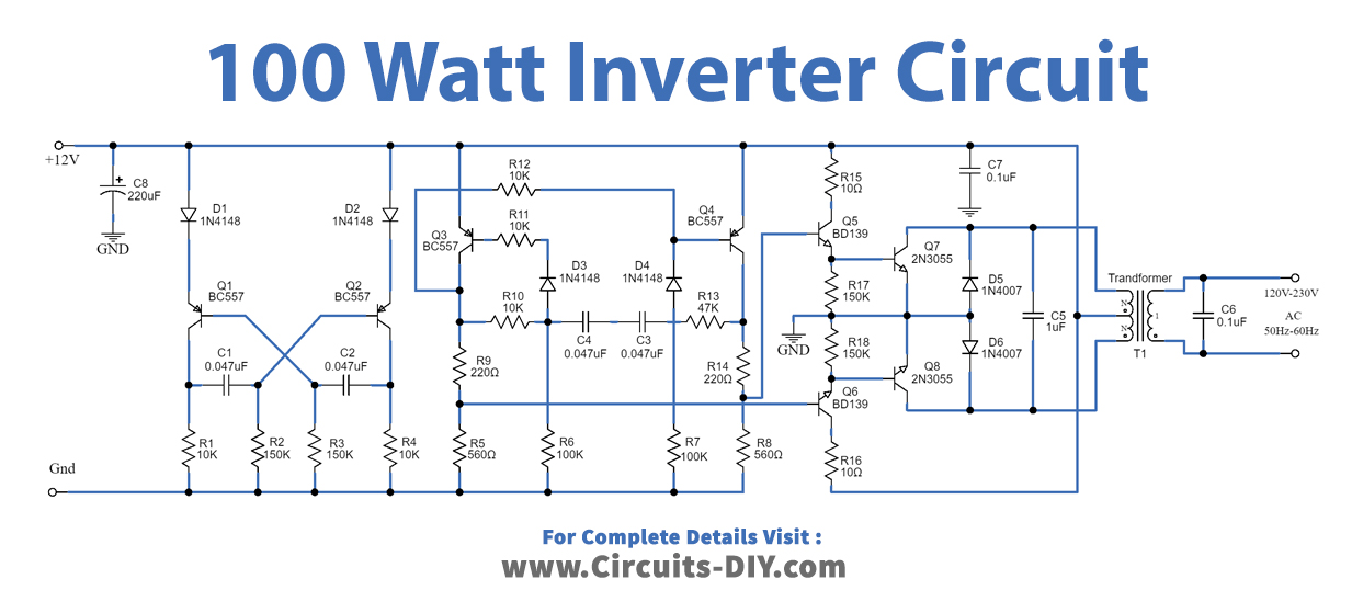
100 Watt Inverter Circuit
Construction and Working
As shown in the circuit 12 V car battery can be used as the 12V source. First, both PNP transistors Q1, and Q2 will be connected as the astable multivibrator form. They will generate a square wave frequency of about 100 Hz at the collector lead of Q2. This frequency is set by both resistors R1, and R2, and two capacitors C1, and C2. And there are both diodes D1, and D2 to set only positive voltage through the emitter lead of Q1, and Q2. Then, this signal flows through to the frequency divider by two. It makes the frequency is reduced down to about 50Hz.
Why designer does not set the circuit to directly work at 50 Hz? Because generating the steady low frequency is too hard. This frequency has valued the same as the AC main. It will be a waveform of low-power alternating current. And, out to the collector leads of transistors Q3, Q4. Then, via resistors R8, R9, and R11, R12. They are a voltage divider circuit biased for driver transistors Q5 and Q6. To drive the power transistors Q7, and Q8 alternately power the high current to the inductance coil in the transformer T1. It will induce electrical energy through the metal core from a set of 12V coils to an AC voltage of 220V at 50Hz to 60Hz for further use. you want 100 watts, so must use an 8A transformer. Use a 9V CT 9V transformer, the output voltage will be 250V (approx.).
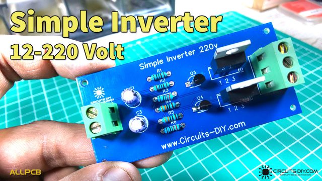
This circuit will have output as a square waveform, So cannot use for inductor load. But it’s enough for mini electrical appliances. Such as electric soldering iron, Digital TVs, Mobile chargers, Small laptops, etc. To begin with, make the PCB or you can use the universal PCB (Perforated PCB). Then, assemble all parts on PCB. Next check all for errors. Check again and check again. Then, apply the 12V 10A battery to this circuit. And use the voltmeter to measure AC voltage output. Next, connects the load to the circuit.
Applications
- This circuit can be used in cars and other vehicles to charge small batteries.
- It can be used to drive low-power AC motors.
- It can be used in solar power systems.