
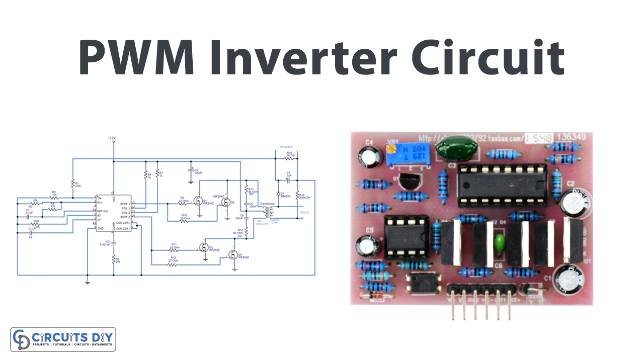
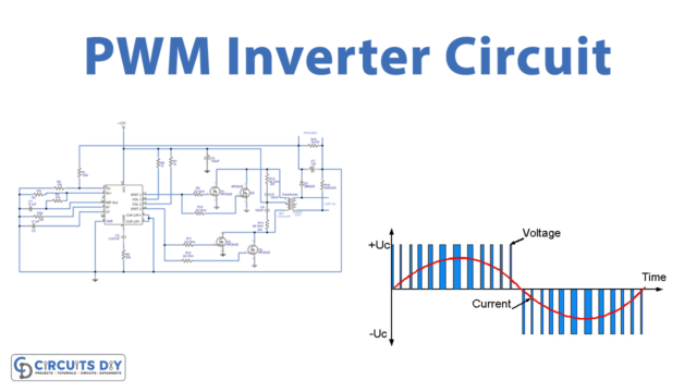
In this tutorial, we are going to make a “PWM Inverter Circuit”. A power inverter is a power electronic device or circuitry that changes direct current (DC) to alternating current (AC). The resulting AC frequency obtained depends on the particular device employed, and gives High voltage and current from a low-power battery source. An inverter whose functionality depends upon the pulse width modulation technology is referred to as a PWM inverter. Most of the inverters available nowadays possess PWM technology and are capable of producing ac voltage for varying magnitudes and frequencies.
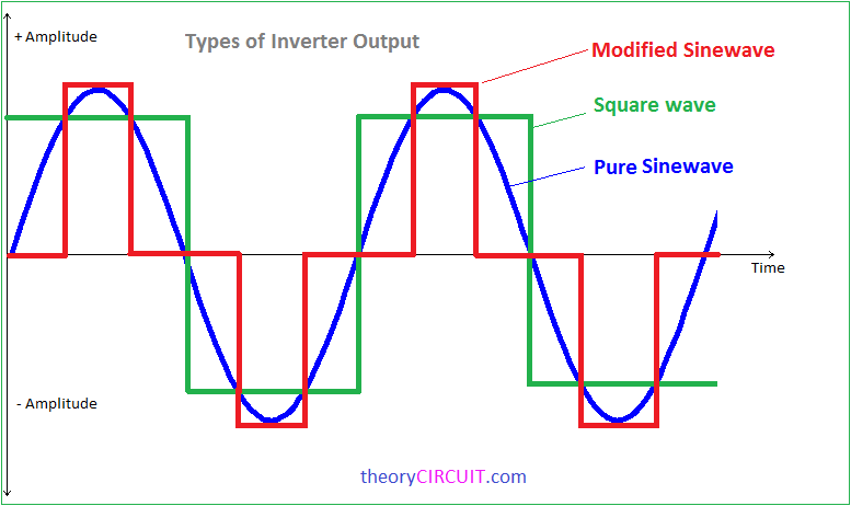
There are multiple protection and control circuits in these types of inverters. The implementation of PWM technology in the inverters makes it suitable and ideal for the distinct loads connected. The inverters based on the PWM technology possess MOSFETs in the switching stage of the output. These are capable of maintaining the output voltages as the rated voltages, this can be achieved by changing the switching frequency width at the oscillator. Inverters can be classified based on the output terms like a square wave, modified sine wave, and pure Sine wave output Inverter.
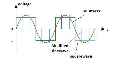
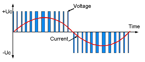
The square wave inverter is very simple and easy to make but that is not suitable for sensitive Electric appliances. Modified sine wave inverters are gives output as close as to the sine wave but not pure as much we have received from the wall outlet. PWM (Pulse Width Modulation) signal-based inverters produce output as a pure sine wave and it can be used for any electric appliance that meets the inverter output range. Here we design a simple and powerful PWM inverter circuit by using IC SG3524 (Regulating Pulse Width Modulator) that gives up to 230V AC from a 12V DC supply.
Hardware Required
| S.no | Component | Value | Qty |
|---|---|---|---|
| 1. | IC | SG3524 | 1 |
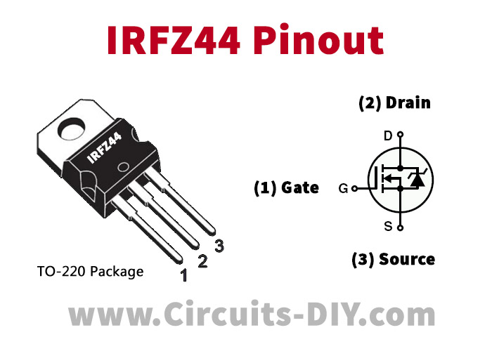
| 2. | MOSFET | IRFZ44 | 2 |
| 3. | Transformer 230V Primary toSecondary | 12-0-12V | 1 |
| 4. | Diode | SB5200 | 1 |
| 5. | Resistor | 4.7KΩ,10KΩ,100KΩ,1KΩ,22Ω, 56Ω/2W,1KΩ/1W,200KΩ/2W | 2,1,2,2,4,2,1,1 |
| 6. | Capacitor | 0.1uf,0.001uf,100uf,100nf,1uf | 2,1,1,2,1 |
| 7. | Battery | 12V | 1 |
| 8. | Connecting Wires | – | – |
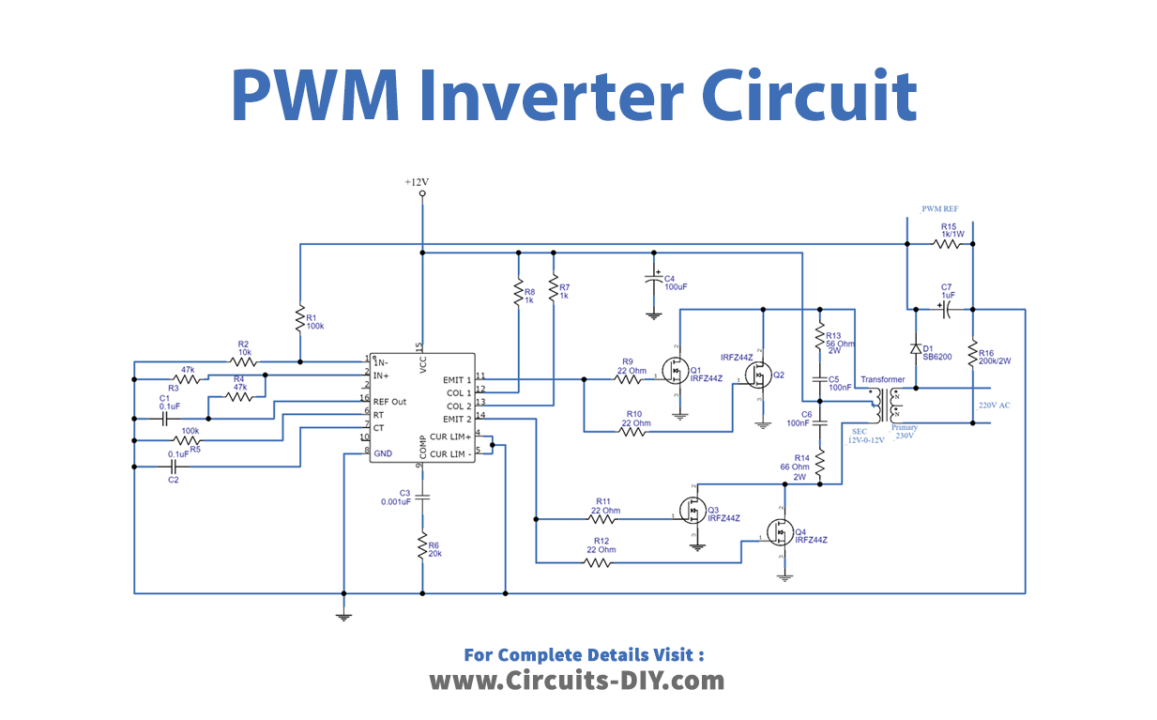
Circuit Diagram
IRFZ44 Pinout
Working Explanation
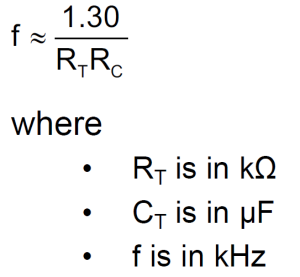
The PWM switching pulse generator is the heart of this circuit, which is responsible to produce a PWM pulse according to the sine wave reference. Here the IC SG3524 gives fixed frequency PWM that can be varied by RT and CT element values.
This Inverter circuit has three stages of operation.
- PWM Switching Pulse Generator
- Switching Device
- Step up Output Driver
Here output from Emit1 and Emit2 pins are directly fed into the switching device, which is constructed by N channel MOSFET IRFZ44. Q 1 and Q2 are driven by Emit1 output, and Q3 and Q4 MOSFET are driven by Emit2 output from SG3524. The step-up output driver contains a transformer 230V primary to 12-0-12V secondary with a 2 Amp current rating, and this transformer is connected in reverse to step up the voltage output. Now to give the reference feedback to PWM regulator SG3524, sample output is taken by the small circuit. Change the RT and CT values to get the required output, and use a heat sink over the MOSFETs. Handle with Care, as it is a high voltage and current output circuit.
Application
Practically these are used in power electronics circuits. Inverters are very helpful to operate electrical appliances during a power cut or shortage.


