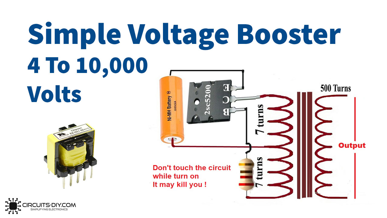
For many of the projects, beginners want to increase the voltages. In simpler words, sometimes it is needed to step up the input voltage source to a higher voltage level. Now, you may arise the question that why there is the need for that when we can use the higher voltages at the input with extremely reasonable and affordable prices. But, not in every circuit, you need the same voltages everywhere. Sometimes you need different voltages at different points. So, to make things easier for you as a beginner, we are going to create a volts booster circuit by using a ferrite core transformer.
Since we are using a ferrite core transformer in this project, before starting, we must know about the specifications of this transformer. The ferric allows the high current resistivity and enables the low eddy current losses over greater frequencies.
Benefits of Ferrite Core Transformer
A ferrite core transformer has so many benefits which make it popular among the other transformers. Hence, widely used in different electronic applications. The ferrite transformer has excellent and high permeability. Moreover, it reduces the Eddy Currents. As you know Ferrite is recognized for its low electrical conductivity and unusual permeability. Therefore, it prevents There is lack of eddy current because of these two advantageous features of the ferrite core. Also, At high frequencies, ferrite core material delivers great performance. So, both, the lack of eddy currents and excellent performance make the ferrite core extremely suitable for higher frequency transformers.
The ferrite core comes in basic two types, hard ferrite core, and soft ferrite core. If we compare both then the soft ferrite cores have a higher coercivity than the high ferrite core. And, hence They are ideal to make them, magnets, etc. Moreover, there is another benefit of soft ferrite cores, that is, they can change the magnetic direction, and very less or negligible hysteresis loss. Aside from the advantages described before, these cores also provide High Q-values, Low, Low DC sensitivity, hysteresis factor, and very little signal distortion
Hardware Components
The following components are required to make Volts Booster Circuit
| S.no | Component | Value | Qty |
|---|---|---|---|
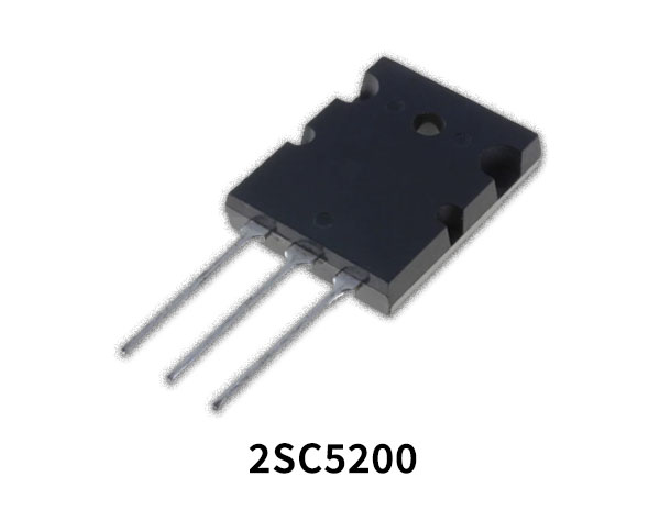
| 1. | Transistors | 2SC5200 | 1 |
| 2. | Resistor | 220 | 1 |
| 3. | Transformer | 4v To 1000v | 1 |
| 4. | Battery | 4V | 1 |
| 5. | Variable Resistor | 10K | 1 |
2SC5200 Pinout
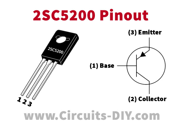
For a detailed description of pinout, dimension features, and specifications download the datasheet of 2SC5200
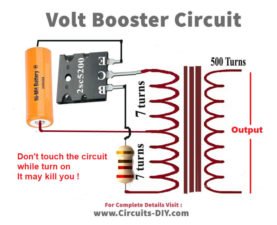
Volts Booster Circuit
Working Explanation
Connect the Volts Booster circuit according to the diagram given in the circuit. Remember, to connect carefully and don’t touch the transformer with your hands once it gets connected. Now, a potentiometer in the circuit is utilized to set and control the frequency. The base of the high-power NPN transistor is connected in series with the resistor and potentiometer to On and OFF the transistor. The emitter is grounded to drain out the current and the current flows through the collector to the transformer. The higher voltage can be observed at the output, that’d why ist has said above that don’t touch the output side of the transformer with your bare hands.
Applications
- Any circuits that need to boost up the input DC to output AC voltage.
- Inverter circuits can also use this circuit.