Introduction
Are you tired of making regular projects and in the search of exciting projects? So, we are here again with a satisfying project of clap switch. To understand the production of energy through sound vibration. The microphone detects the intensity of the sound. Inside the microphone, there is a diaphragm. When the clap sound hits the diaphragm, it vibrates and changes the capacitance. With the changing of capacitance, voltage changes and that’s how it takes and passes the signal forward which we will discuss in the working explanation. In other words, the load of this circuit gets turned on or off by the human hand clap. This simple circuit is very suitable for beginner of electronics students who are also willing to research different sources of energy. So, in this tutorial, we are going to make a “Clap switch circuit using IC 555”
Hardware Required
| S.no | Component | Value | Qty |
|---|---|---|---|
| 1. | IC | NE555 Timer | 1 |
| 2. | Condenser Mic | – | 1 |
| 3. | Transistor | BC547 | 2 |
| 4. | LED | – | 1 |
| 5. | Capacitor | 0.1uF, 100uF | 2,1 |
| 6. | Resistor | 330Ω, 10KΩ, 470Ω, 1KΩ, 4.7KΩ | 1,1,1,1,1 |
| 7. | Battery | 6v | 1 |
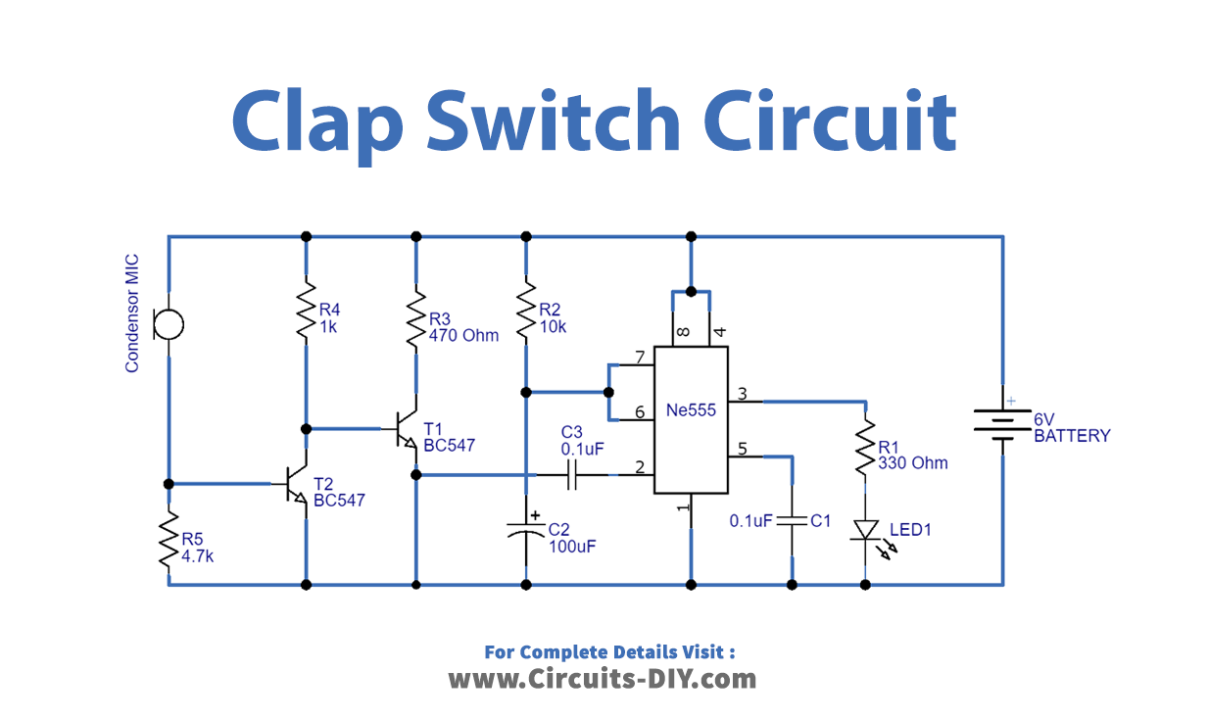
Circuit Diagram
Working Explanation
In this Clap switch circuit using IC 555, the condenser mic is working as a sound sensor. Hence, it will generate voltage oscillation when there is a sound. After that, these voltage oscillations get amplified by two BC547 transistors which is working as a two-stage amplifier. We then provided the output of this two-stage amplifier to trigger input pin 2 of IC555. The timer IC generates the pulse depending on the timing resistor and capacitor. Output is coming from pin 3, therefore LED is connected at that pin.
Application and Uses
- We can use it in hearing aid devices.
- Also, in tape recorders.
- In speech recognition devices.
- Further, Sound-sensitive LED lights