Introduction
Looking for a reliable and efficient way to charge your NiCd batteries? You’re in luck! In this blog, we will explore not one but three different circuits designed to charge NiCd batteries efficiently.
Each of these circuits has unique features and benefits, from the flexibility to substitute components to the inclusion of protection against improperly polarized input voltages. So, let’s dive into these versatile circuits’ hardware requirements, schematics, and workings and discover the best fit for your needs.
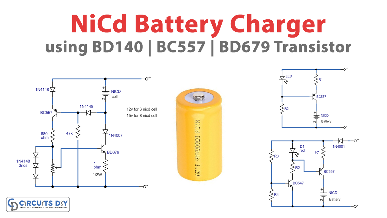
Circuit 1
Schematic
Hardware Required
| S no | Components | Value | Qty |
|---|---|---|---|
| 1 | Transistor | BC557, BD679 | 1, 1 |
| 2 | Capacitor | 470nF | 3 |
| 3 | Resistor | 680, 47k, 1k | 1, 1, 1 |
| 4 | Diode | 1N4148, 1n4007 | 5, 1 |
| 5 | V. Resistor | – | 1 |
Working
Firstly, recharging numerous NiCd batteries in a row with this charger is a breeze. Because it can handle up to 8 cells. If 1.65 volts increases the power source for each added cell, the number of cells that can be charged may increase. If the BD679 is mounted on a high-quality heatsink, the input voltage can be raised to a maximum of 25v. The battery will not discharge when the charger is disconnected from the power source. Fully charging a NiCd battery at a 14-hour rate is usually required, which means recharging the battery at 10% of its capacity for 14 hours. This is valid for a nearly-dead cell, such as a 600mAh cell that can be fully charged at 60mA for 14 hours. Excessive charging current, on the other hand, can cause the cell to be damaged.
The 1k pot regulates the charging current degree between 0mA to 600mA while the appropriate polarity of NiCd cells is connected, and BC557 is initiated. Without a BD679, we can source a substitute with any NPN Darlington transistor possessing an average power and nominal voltage of 30v and current efficiency of 2A. If the one-ohm resistor value is reduced to 0.5 ohms, the maximum output current will be enhanced to 1A.
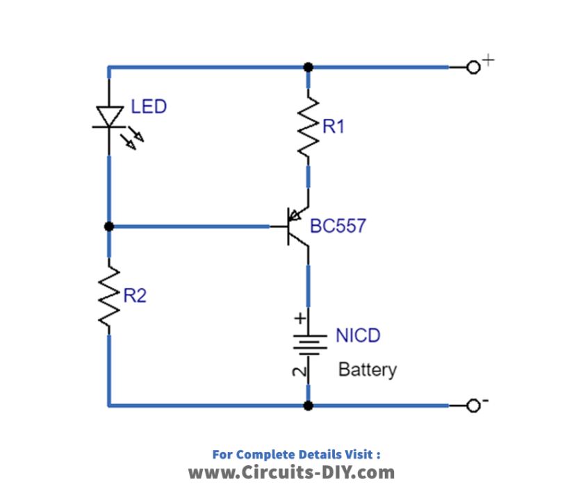
Circuit 2
Schematic
Hardware Required
| S no | Components | Value | Qty |
|---|---|---|---|
| 1 | Transistor | BC557 \ BD140 | 1 |
| 2 | NICD Battery | – | 1 |
| 3 | Resistor | – | 2 |
| 4 | LED | RED | 1 |
Working
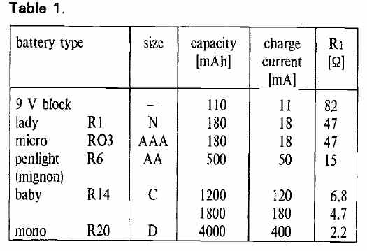
The above circuit has the reference voltage obtained from the forward drop across a red LED (approximately 1.5 V). To maintain a 1.5 V difference between the positive supply rail and the base of T1, the current flowing through the LED is limited by resistor R2. The voltage across resistor R1 is estimated to be 0.85 V, which can be used with the formula IB = 0.85R1 to determine the charge current for the battery. Typically, the current is not dependent on the circuit’s supply voltage.
Calculating the value of R1 is straightforward because NiCd batteries are usually charged with a current equal to 1/10 of their capacity. The table below provides R1 values for various battery types.
If there is no battery, LED D1 will switch off due to the decrease of voltage passing through resistor R1. As a result, the current flowing through resistor R2 will shift and pass through both resistor R1 and transistor T1’s base-emitter connection.
Circuit 3
Schematic
Hardware Required
| S no | Components | Value | Qty |
|---|---|---|---|
| 1 | Transistor | BC557 \ BD140 BC547B | 1 1 |
| 2 | LED | RED | 1 |
| 3 | Resistor | 3.3k | 4 |
| 4 | Diode | 1N4001 | 1 |
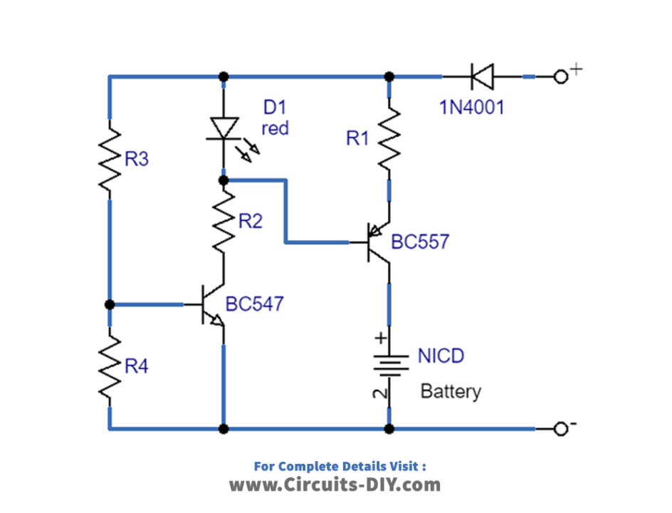
Working
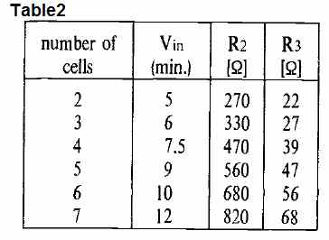
This above-given circuit features a diode that serves as protection against input voltages that are improperly polarized, preventing damage to the circuit. R3, R4, and T2 are also included in the circuit to disable the charger when the input voltage is not adequate. The table below lists the values for R2 and R3 based on the number of 1.2V cells in the NiCd battery.
While any PNP transistor may be used in the T1 position if the charge current remains under 100 mA, it is recommended to use a medium-power transistor from the BD series for better management of higher input voltages or change currents. Input voltage does not need to be highly regulated or smoothed out, and any adapter that produces sufficient output voltage and current may be used. Hence, depending on the number of cells in the NiCd battery configuration, the charge current may also be obtained from a 12V car battery.
Final Thoughts
In conclusion, the NiCd battery charger circuit using transistors is a brilliant example of how we can use technology to make our lives easier and more efficient. With the help of this circuit, you can charge your NiCd batteries quickly and easily without worrying about damaging them.
These circuits are not only simple but also highly effective. Hence, with a little effort and some basic knowledge of electronics, you can build these circuits and enjoy the benefits of a reliable and efficient battery charger.
We hope you found this article informative and interesting. If you have any questions or queries about the circuit, please do not hesitate to comment below. We are always happy to help and share our knowledge with our readers. Thank you for reading, and we hope you like the circuit!