Introduction
Welcome to our ultimate guide on how to make a constant-current battery charger circuit! As we all know, batteries play a significant role in our daily lives, powering our favorite devices like smartphones, laptops, and electric vehicles. However, these batteries tend to lose their charge over time, leaving us stranded when we need them the most. That’s where a reliable battery charger comes into play, enabling us to recharge our batteries effectively and quickly. This guide will walk you through creating different constant-current battery charger circuits, giving you the power to revive your exhausted batteries and keep them charged for extended periods.
No matter how tech-savvy you are or how much you like DIY projects, our guide is made to fit your needs. It gives you all the information you need to make a high-quality battery charger from scratch. So, get ready to learn valuable insights on building your constant-current battery charger circuit and take a step towards becoming a self-sufficient electronics pro!
Circuit 1: Single Resistor Method
Hardware Required
| S.no | Components | Value | Qty |
|---|---|---|---|
| 1 | Limiting Resistor | R | 1 |
| 2 | Battery | 12V (Cell Series) | 4 |
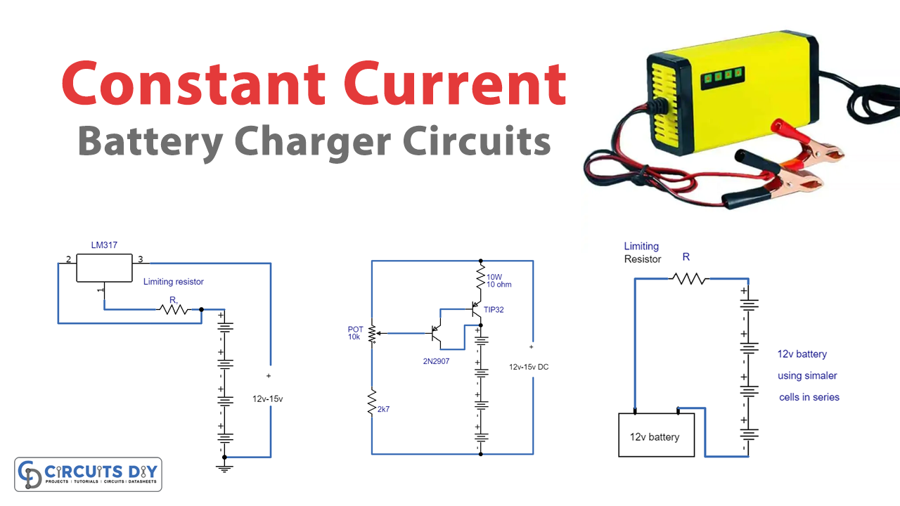
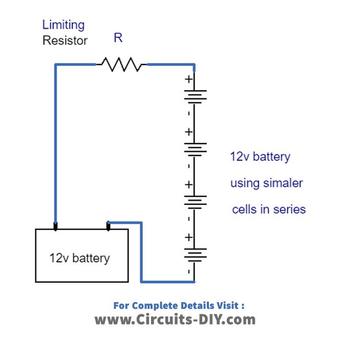
The first circuit uses a single resistor to establish the required charging current. For instance, if four large batteries need to be recharged at a rate of 500 mA from a 12-volt battery, the resistor required would be 23.3 ohms. Alternatively, a value of 20.2 ohms may be more suitable.
Circuit 2: Single Darlington BJT Method
The second circuit design incorporates a single Darlington BJT (Bipolar Junction Transistor) to control the charging current. This circuit is helpful in situations where moderate power is required, and the circuit’s simplicity is an advantage.

| S no | Components | Value | Qty |
|---|---|---|---|
| 1 | Transistor | 2N2907, Tip32C | 1 |
| 2 | Potentiometer | 470nF | 3 |
| 3 | Resistor | 10, 2k7 | 1, 1 |
| 4 | Battery | 12V | 4 |
| 5 | V. Resistor | 10K | 1 |
The voltage on the emitter of the TIP32 transistor will likely be 1.5 volts higher than the voltage on the POT slider. When the POT is fully upward, the transistor will be turned off, and the current will be close to 0 volts.
To regulate the current across the output and the 10-ohm resistor, a POT is used to determine the voltage on the TIP32 emitter. If the output is overloaded, the TIP32 transistor may waste up to 7 watts and requires a large heat sink.
If the maximum amount of current goes through the 10-ohm resistor, it could produce about 7 watts of heat, so a wattage of 10 or more may be needed.
If more than four cells are connected, the maximum current available may decrease and limit the current adjustment to approximately 100 milliamps for ten cells. The typical charging rate for high-capacity (4AH) ‘D’ cells is 300 to 400 milliamps for 13 hours and 100 milliamps for (1.2AH) ‘C’ or ‘D’ cells. For smaller 9-volt batteries, the charging rate can be 7 milliamps, and you can decrease the range to 0-20 mA by using a 750 ohm resistor instead of 10. To set the charging current, you can connect an ammeter to the output (making sure all batteries are disconnected) and adjust the pot to the desired current or monitor the voltage across the 10-ohm resistor (1 volt = 100 mA) or (1 volt = 1.33 mA with a 750 ohm resistor).
Circuit 3: LM317 IC Method
Finally, the third circuit uses the LM317 IC (Integrated Circuit) for its current controlled charging system. This circuit is the most sophisticated of the three and is ideal for precision charging.

| S no | Components | Value | Qty |
|---|---|---|---|
| 1 | Voltage Regulator | LM317 | 1 |
| 2 | Limiting Resistor | R | 1 |
| 3 | Battery | 12V | 4 |
Simply connecting a resistor (R) between the load and the end terminal while connecting the wiper terminal with the load, will create a constant current of 1.25/R, as the voltage at the middle of the wiper port and end terminal is 1.25 volts. To obtain a charging current of 100mA, a resistor (R) of twelve ohms may be used, whereas for a current of one amp, a 1.2 ohm 2-watt resistor is required. A diode can be added in series with the input to prevent any reverse voltage from the battery packs to the regulator IC when power is turned off, and the batteries remain connected. It is advisable to disconnect the batteries before switching off the supply voltage.
Final Thoughts
In conclusion, constant current battery chargers are essential for ensuring the longevity and functionality of batteries, especially in devices that require consistent power. These circuits come in different configurations and designs, each with unique features and advantages that meet specific charging needs.
Whether experimenting with electronics or repairing an old device, understanding the basics of constant current battery charger circuits is vital. With this knowledge, you can choose the right charger and prevent damage to your device’s battery, saving you time, money, and frustration in the long run. So, try these circuits and increase your circuit-building skills. Happy learning!