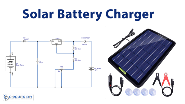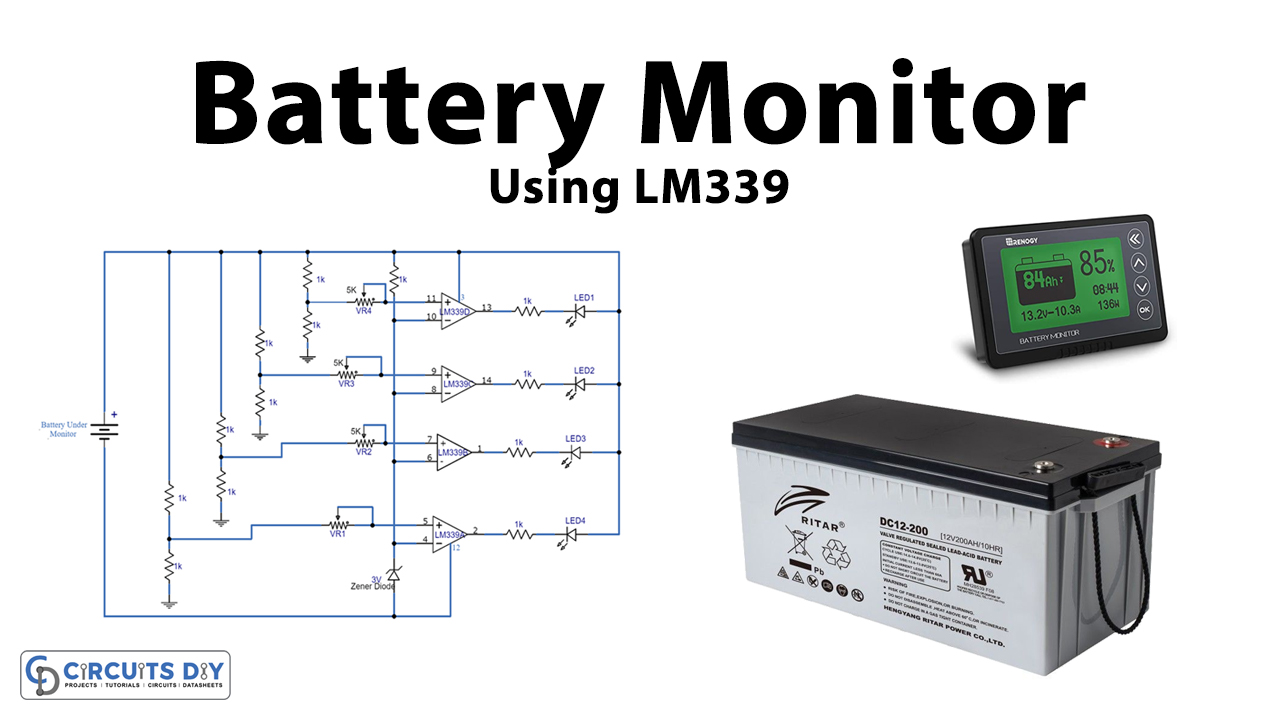
Here is a circuit of a Battery Monitor using the LM339 IC. Battery monitors are useful circuits that help in saving your batteries from deep discharge or complete discharge. When the battery level of a rechargeable battery falls below 50% of its capacity it gets discharged but with this monitor, you will be able to know beforehand. This circuit can be used with a variety of rechargeable batteries of different kinds and voltages and is user-friendly.
Hardware Components
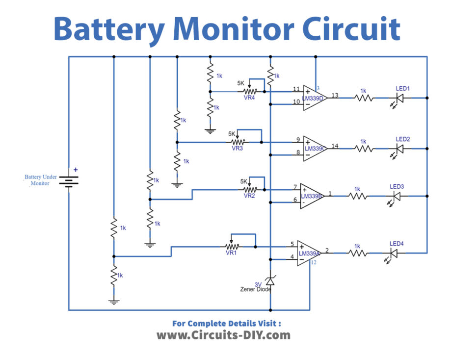
Battery Monitor Circuit
| S.no | Component | Value | Quantity |
|---|---|---|---|
| 1. | Battery | 12V | 1 |
| 2. | IC | LM339 | 1 |
| 3. | LED | – | 4 |
| 4. | Resistor | 1K | 12 |
| 5. | Variable Resistor | 5K | 1 |
| 6. | Zener diode | 3V | 1 |
LM339

For a detailed description of pinout, dimension features, and specifications download the datasheet of LM339
Battery Monitor Circuit
Working Explanation
The heart of this circuit is an operational amplifier IC LM339. It has four independent op-amps, each of which is used as a comparator in this circuit to detect different voltage levels. Variable resistors of 10K are connected with each op-amp to set their voltage level.
To monitor a battery it’s important to know the full and half voltage of a battery. For example, a 12V battery fully charged will show 12.6V, and when it’s 50% used it will show 12.1V on a multimeter. We are supposed to charge our batteries when they are 50% empty to save them from getting discharged.
Circuit Tuning
- Take a variable power supply and set the voltage to 12.5V and replace it with the battery of the circuit.
- Adjust the VR1 slightly until LED1 turns on.
- Change the voltage of the adjustable power supply to 12.4V.
- Adjust the variable resistor VR2 slightly until LED2 turns on.
- Change the voltage to 12.3V in the power supply and adjust the VR3 until LED 3 turns on.
- Again change the voltage to 12.1V and adjust the VR4 this time until LED 4 goes on.
- After these adjustments do a final check by increasing the voltage of the adjustable power supply to 12.6V and slightly down to 12.1V. At this point, all the LEDs will go on one by one at their preset voltages.
Now your circuit will be ready to use. These settings are for a 12V battery, the same procedure will be followed for other batteries.