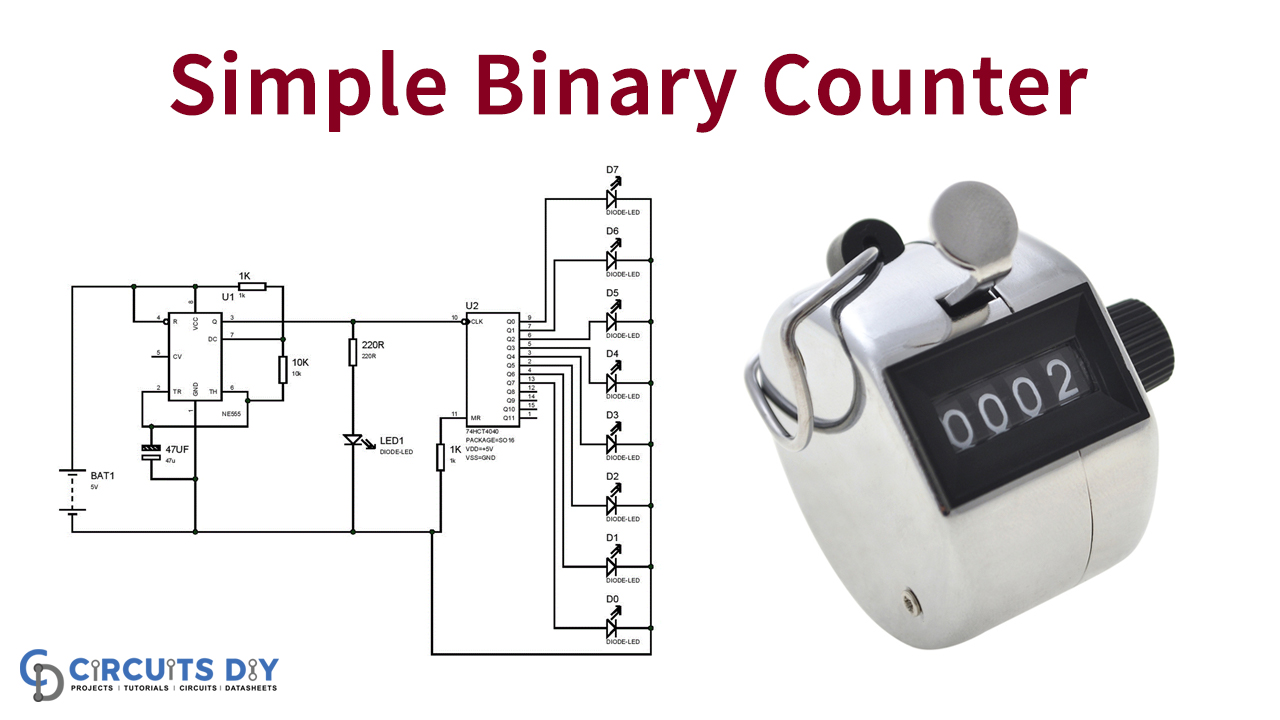
One of the most significant electronic components is a 555 Timer IC due to its versatility. This IC helps you to create various types of circuits. This circuit includes an LED blink for each half-second, and a square waveform of 555 timer IC is connecting with an 8bit (74HC4040) BINAY counter.
Here is the basic circuit using 555 Timer IC as an ASTABLE MULTIVIBRATOR. Whenever a timer produces a pulse, it is counted and stored in the binary counter. The following section further on the operation of this circuit is covered.
Hardware Components
The hardware components required to make 555 Timer Based Binary Counter are:
| S.no | Component | Value | Qty |
|---|---|---|---|
| 1. | Power supply | 5 V | 1 |
| 2. | Capacitor | 47 uF | 1 |
| 3. | Resistor | 220 ohm, 10k, 1k | 1,1,1, |
| 6. | IC | NE555 | 1 |
| 7. | Binary counter IC | HD74HC4040 | 1 |
| 8. | Breadboard | – | 1 |
| 9. | Connecting wires | – | – |
| 10. | LED | – | 9 |
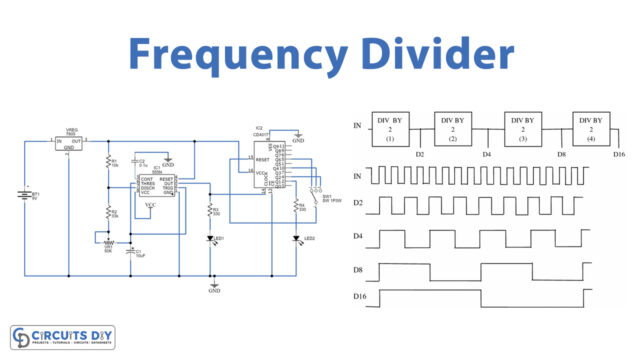
Circuit Diagram
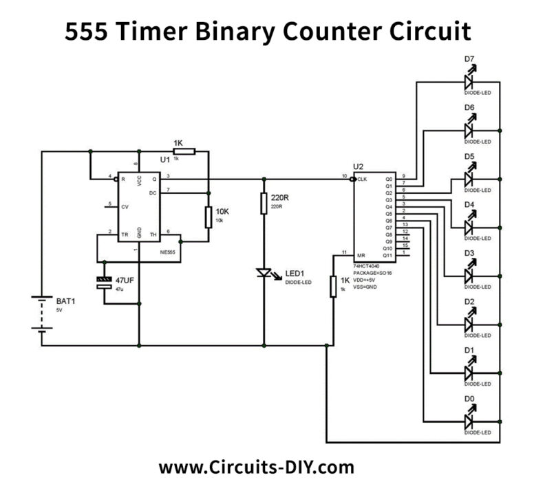
Circuit Operation
The circuit architecture begins with the generation of 555 IC square waves. After all the components have been put in the above circuit diagram, the “LED1,” at a rate of half a second, must be blinking. The higher the capacitor’s value, the lower the blink rate may change to adjust the blinking speed. However, it is not sufficient to pick a capacitance above 100uF and below 4.7uF.
The blinking frequency slows considerably above 100uF and may have been mistaken as a failure circuit. Where lower capacitance is selected, the blinking is too fast to catch the human eye and may be believed to be a failure. It is also recommended to verify the capacitance value when selecting a capacitor. The binary counter will directly drive the LED so that resistors are not required at the end of the binary counter LEDs.
Applications and Uses
Counters may be used for a wide range of applications. They may be used to determine, for example, the number of revolutions that can be used for measuring the speed of a motor to pulses in a sensor connected to a motor. Counters may also be used for various applications as digital clocks.