Introduction:
A frequency divider as the name indicates is a circuit that generates output frequency which is the integral multiples of the applied input frequency. It is also known as pre-scalar or clock dividers. Different electronic devices such as regenerative devices relaxation generators etc. are used for the division of frequency. There are three main types of frequency dividers analog, digital, and fractional-n dividers.
Frequency dividers can be simple or complex circuits depending upon the application. The simple circuit can be built using a 555 timer IC which is used as an oscillator or timer in different circuits and a CD4017 IC which is a ten output decoder IC that can be used as a counter or divider. The aim is to provide a simple and easy-build circuit to understand the concept of the frequency divider.
Hardware Components
The following components are required to make Frequency Divider Circuit
| S.no | Component | Value | Qty |
|---|---|---|---|
| 1. | IC | NE555 timer | 1 |
| 2. | Decade Counter IC | CD4017 | 1 |
| 3. | Voltage Regulator IC | 7805 | 1 |
| 4. | Variable Resistor | 50KΩ | 1 |
| 5. | LED | – | 2 |
| 6. | Switch | – | 1 |
| 7. | Battery | 9V | 2 |
| 8. | Resistor | 33KΩ, 10KΩ, 330Ω | 1, 1, 2 |
| 9. | Capacitor | 10μF, 0.1μF | 1 |
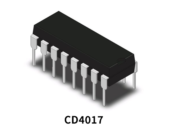
CD4017 Pinout
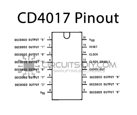
For a detailed description of pinout, dimension features, and specifications download the datasheet of CD4017
NE555 IC Pinout

For a detailed description of pinout, dimension features, and specifications download the datasheet of 555 Timer
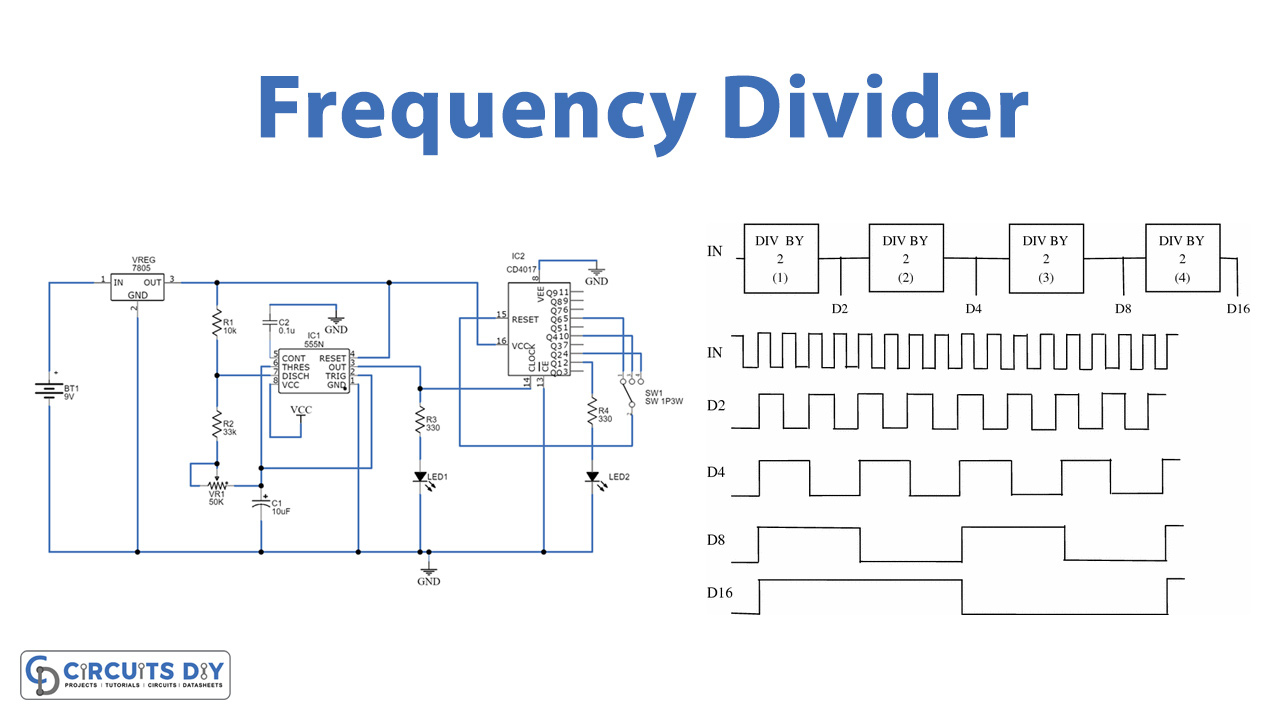
Frequency Divider Circuit
The circuit diagram for the frequency divider is given below:
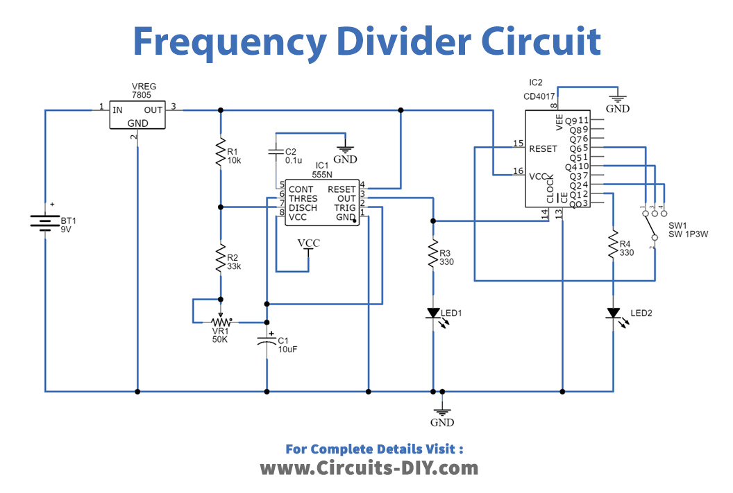
Construction & Working:
The two major components of the circuit are 555 timer IC and CD4027 IC along with other passive components to complete the circuit and work in a desirable way.
Here the 555 timer IC is used as a pulse generator to divide the frequency. The IC has been found to be applicable for different purposes like timing or oscillation generator or pulse generator etc. the IC CD4017 is used as a divider to divide the frequency in multiples. It produces ten decoded outputs, generally used as a divider or counter.
The circuit works in two steps, the first in the input frequency generator while the second is the decoder or divider circuit. The 555 timer IC is configured in the astable mode. The discharge pin of the IC is connected in between the two resistors R1 and R2 (timing resistors), which in series are connected to the variable resistor VR1 and to the timing capacitor C1. The threshold and trigger pins are coupled together and connected in between the VR1 and C1 while the 5V input is connected to the reset and VCC pins coupled together. The output of the timer IC is connected to the 4017 IC while the two LEDs indicate the input frequency.
The pin14 of the 4017 IC receives input and delivers the decoded output from Q0 to Q9, the output is taken from pin2 after converting it into a frequency divider while the LED indicates the output. The frequency-divided output can be seen using an oscilloscope from pin2. The reset pin is connected with a switch towards Q2, Q4, and Q6 for the selection of F/2, F/4, and F/6 outputs respectively.
Applications:
The frequency divider can be implemented in different analog and digital circuits, it has the following applications:
- The circuit is used in frequency synthesizers to generate a range of frequencies from a single input.
- It is also used in atomic clocks or in television sets.
- The circuit is also applicable in radar systems as a timing device.
- The circuit is used to make ‘n’ multiples of the frequency which can be used in clock buffer circuits.
- It also finds application in RF devices, audio and military equipment, etc.