Introduction:
A timer is a special purpose clock that is used for measuring particular time intervals. It is highly applicable in our daily life devices or equipment to switch the load for a certain amount of time. The timers can be executed either as a hardware tool or can be programmed in the software.
The timer circuit can be built using a simple IC or a microcontroller depending upon the application in which the timer is to execute. Here we will discuss a simple circuit that uses a 555 timer IC in a monostable mode to generate alerts for variable limits of time. The circuit is easy to build and uses minimum components for the timer to work. The buzzer is used to generate alerts for the specified time limits. This circuit is useful in many applications.

Hardware Components
The following components are required to make an Adjustable Timer Circuit
| S.no | Components | Value | Qty |
|---|---|---|---|
| 1. | IC | NE555 Timer | 1 |
| 2. | Buzzer | 9V | 1 |
| 3. | Variable Resistor | 1MΩ | 1 |
| 4. | Resistors | 10KΩ & 10Ω/1W | 1 each |
| 5. | Capacitor | 1000μF/16V | 1 |
| 6. | Push-button switch | – | 1 |
| 7. | Battery | 9V | 1 |
NE555 IC Pinout

For a detailed description of pinout, dimension features, and specifications download the datasheet of 555 Timer
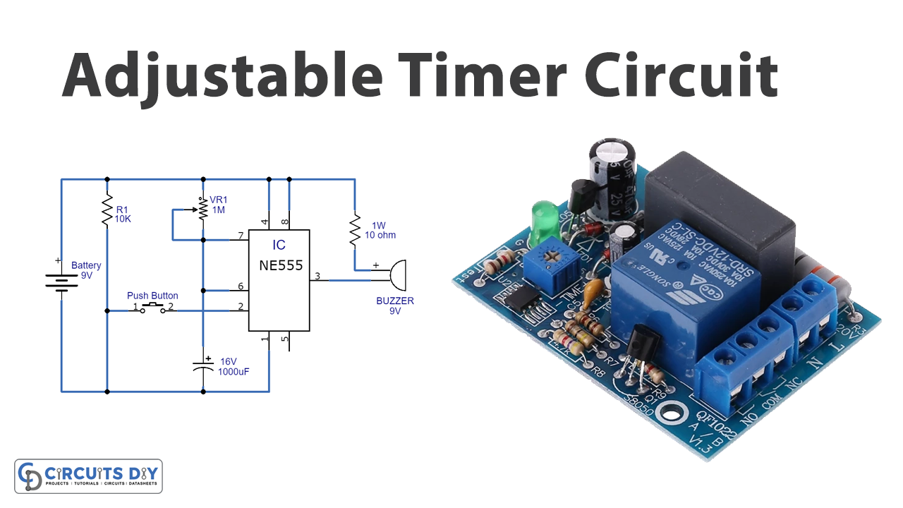
Adjustable Timer Circuit
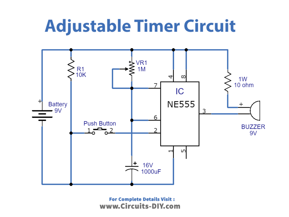
Working Explanation:
The circuit uses 555 timer IC as its key component along with the variable resistor which is used to change the time duration of the output pulse, a buzzer used to produce alerts, and a few other components.
The IC is used in a monostable mode. The IC is disconnected from the supply through the switch at Pin2 (Trigger pin). When the switch is pressed, the trigger pins get the negative supply, and thus the IC is triggered. The variable resistor and capacitor also called timer elements are connected across the power supply and threshold pin. The output pin is connected to the buzzer through a resistor R2. The positive end of the battery is connected to pin1 of the IC while the negative end is connected with pin8 which is coupled with pin4.
When the input is applied to the circuit, the timer generates a pulse whose width is dependent on the values of the resistor and capacitor. The minimum delay of one minute is attained when the pot is at a minimum value and the maximum value of the pot gives the delay of 10 minutes.
Applications:
Timers are used in various applications in our daily life.
- It can be used in washing machines, microwave ovens, sandwich makers, etc.
- It can also be used in traffic light systems, printing applications, pump control systems, etc.
- It can be applicable in industries like cooler control systems.
Thus, the adjustable timer is applicable in various commercial and residential applications.