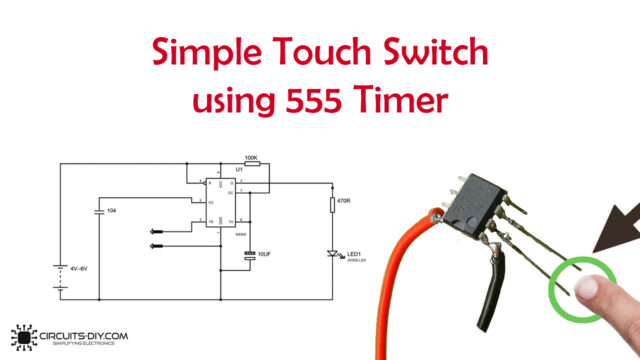
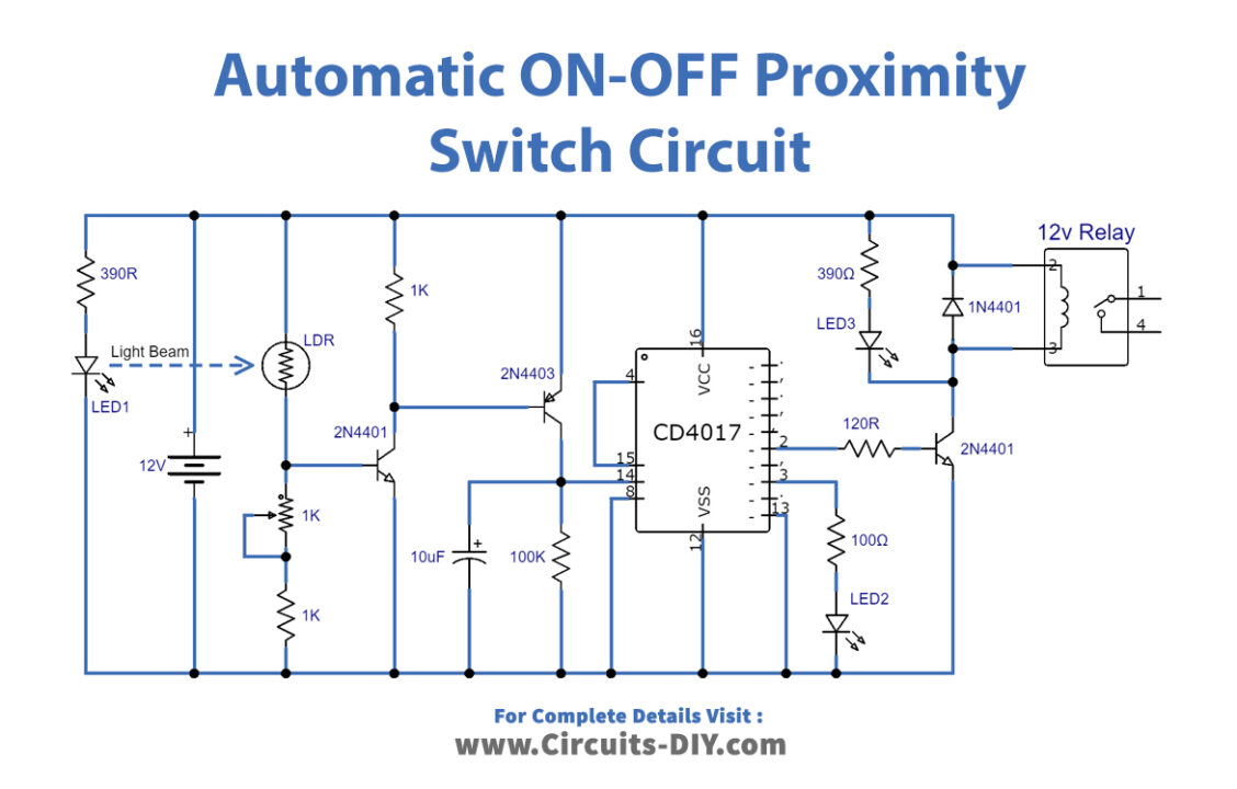
In this tutorial, we are going to make an Automatic ON-OFF Proximity Switch Using CD 4017. As the name suggests Proximity switches are used to sense the presence when some person or object is brought close in proximity and it turns the appliances connected to it ON & OFF accordingly. Whenever you enter a room where this circuit is present it will turn on the Lights automatically and turn them off when you leave.
The IC CD 4017 is a decade counter cum decoder circuit, it is very useful and beginner-friendly. It is acting as a toggle for this circuit. For sensing purposes, we are using a combination of LED and LDR.
Hardware Components
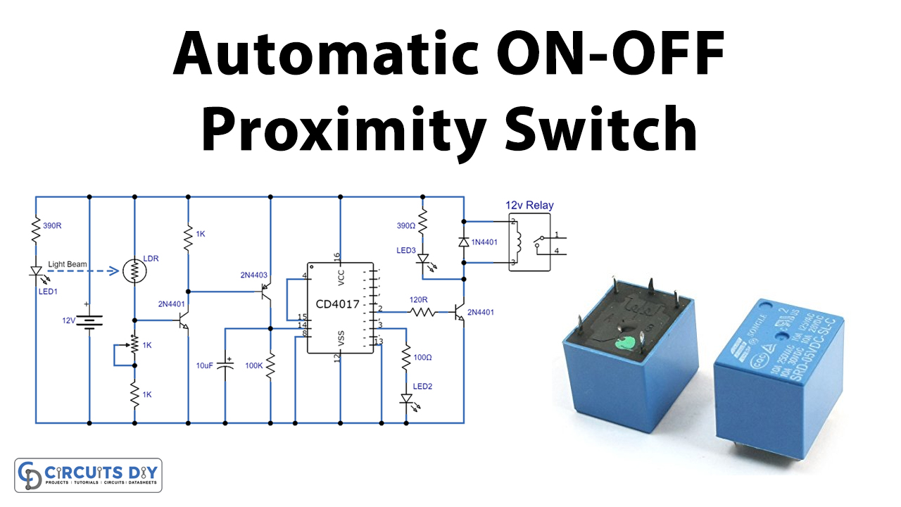
Automatic Proximity Switch Circuit
| S.no | Component | Value | Qty |
|---|---|---|---|
| 1. | Battery | 12V | 1 |
| 2. | LEDs | – | 3 |
| 3. | LDR | – | 1 |
| 4. | Transistor | 2N4401, 2N4403 | 1, 1 |
| 5. | Resistors | 390R,1K, 100K, 390Ω, 100Ω, 120R | 1, 2, 1, 1, 1, 1 |
| 6. | Variable Resistor | 1K | 1 |
| 7. | Electrolytic Capacitor | 10µF | 1 |
| 8. | Diode | 1N4001 | 1 |
| 9. | Relay | 12V | 1 |
| 10 | Counter IC | CD4017 | 1 |
CD4017 Pinout
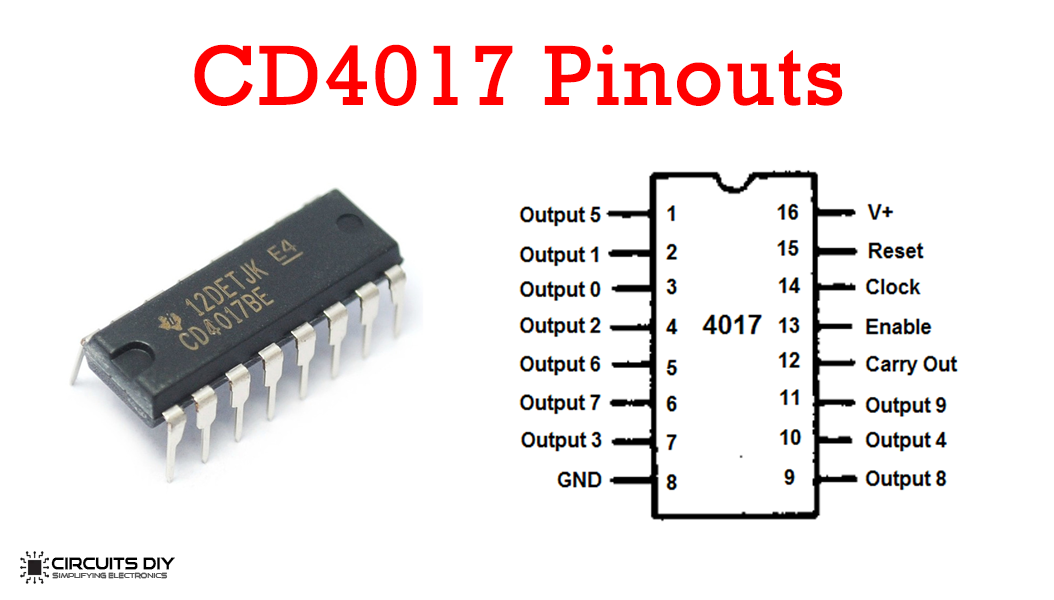
For a detailed description of pinout, dimension features, and specifications download the datasheet of CD4017
2N4401 Pinout
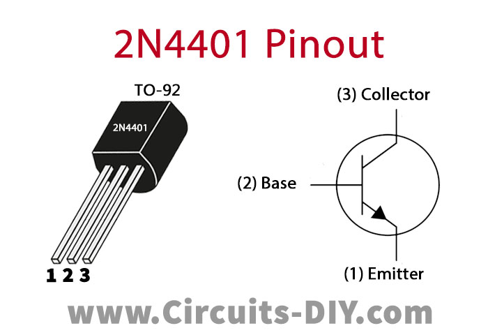
For a detailed description of pinout, dimension features, and specifications download the datasheet of 2N4401
2N4403 Pinout
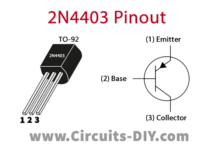
For a detailed description of pinout, dimension features, and specifications download the datasheet of 2N4403
Automatic Proximity Switch Circuit
Circuit Placement
This circuit requires a proper fitting to work since LED1 is continuously providing a light beam to the LDR. You have to use two boxes and place them on both sides of the door parallel to each other. In the first box fit LED1 with a resistor and in the second box the remaining circuit so that the LDR can continuously receive the light properly.
Working Explanation
This circuit is further divided into two parts, the first part contains a light/dark sensor circuit and the second part has a CMOS decade counter IC which works as a toggle switch. Let’s take a look at the working of both parts.
Light/Dark Sensor Circuit
In the first part, LED1 is continuously giving light to the LDR and its resistance is minimum therefore it sends all the voltage to the ground and keeps the circuit OFF. When any person or object will pass through the door and blocks the light LDR’s resistance will be maximum and all the voltage will pass to transistors.
Toggle Switch Circuit
After the activation of transistors second part of the circuit activates, decade counter IC CD4017 will now receive input and the output of this IC will activate the relay switch. Any appliance connected with the relay will switch on. The same happens when any person/object will pass again through that door, the LED beam will be interrupted again and the relay switch will turn off switching any appliance connected to it off too.
Applications and Uses
- Elevators
- Garages
- Washrooms
- Electronic Projects
- Object Counters