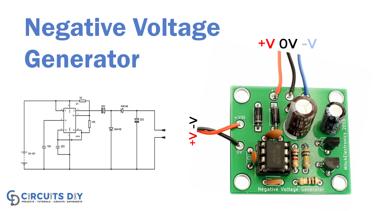
In this tutorial, we are developing a project for a Negative Voltage Generator that is easy to make and requires a few low-cost components. In electronic applications, often, we require negative voltage. However, having a negative supply source is not a reliable alternative when it requires for low current applications.
We can not go for a negative voltage power supply for many electronic circuits that need low power. For the applications of reference or low power purposes, one may go for circuits that can produce negative voltage from a positive voltage supply.
To this end, there are various loops. Here, a basic negative voltage generator circuit was built. This circuit is constructed from a 555 timer IC circuit.
Hardware Component
The following components are required to make a Negative Voltage Generator Circuit
| S.no | Component | Value | Qty |
|---|---|---|---|
| 1. | Supply voltage | 5 to 9 V | 1 |
| 2. | IC | NE555 timer | 1 |
| 3. | Resistor | 1KΩ, 10KΩ | 1 |
| 4. | Ceramic Capacitor | 22nF, 100nF | 1 |
| 5. | Electrolytic Capacitor | 22µF | 2 |
| 6. | Diode | IN4148 | 1 |
| 7. | Testing probes | – | 1 |
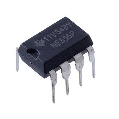
NE555 IC Pinout

For a detailed description of pinout, dimension features, and specifications download the datasheet of NE555 IC
Negative Voltage Generator Circuit
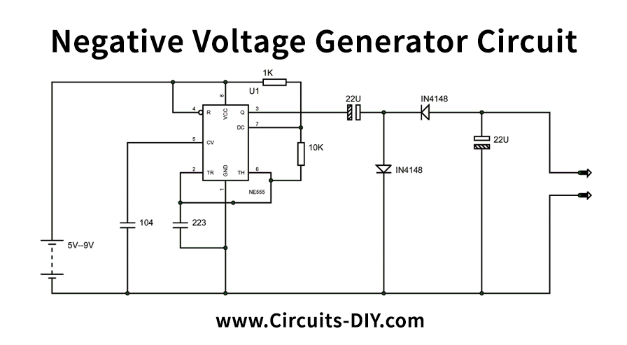
Working Explanation
The figure above shows the negative voltage generator circuit diagram. The 555 timer IC here is a vibrator ASTABLE. The capacitor can be modified, so for the full negative voltage. The selection should be finished. If the capability is not chosen, the optimal negative tension at the output can not be reached.
The 555 Timer IC functions as a square wave generator and produces a square wave, as previously mentioned. The square has a positive peak and +0 a complete loop.
There will now be a current flow (REDLINE), as seen in the figure below when the voltage peak at the output is positive. The D1 diode will prefer forward at this time, and the D2 diode will be reversely preferred.
Consequently, the capacitor C1 is filled, as shown in the figure, and VCC voltage occurs over it.
If the ground emerges after a positive peak, the current (RED LINE) flow will continue, as illustrated above. The diode D1 is reverse biased at this time, and the diode D2 is biased forward. The load deposited in the C1 capacitor would have a way of flowing when D2 is failed. Thus the capacitor C1 discharges through D2, the capacitor C2 being charged. The figure shows this. Therefore, a voltage will occur in the C2 capacitor throughout the 0 V signal.
The voltage on C2 is negative if the ground is affected. This constant charging and uploading for each loop and constant negative voltage through the output of the ground.
Applications and Uses
We can not use a negative voltage power source for many electronic circuits that need low power. One may use circuits to produce negative voltage from a positive voltage supply for referencing or low power applications.