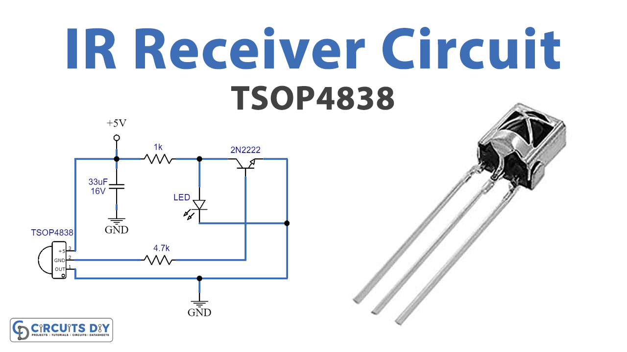
An IR receiver circuit is a simple circuit including an IR receiver and a transistor. In this circuit, the receiver used is a 38kHz transmitter TSOP4838. It receives an IR signal and Turns ON an LED at Output connected with a 2n2222 transistor.
Hardware Components
The following components are required to make the IR Receiver Circuit
| S.no | Component | Value | Qty |
|---|---|---|---|
| 1. | IR Receiver | TSOP4838 | 1 |
| 2. | Transistor | 2N2222 | 1 |
| 3. | LED | – | 1 |
| 4. | Battery | 6V to 12V | 1 |
| 5. | Resistor | 1KΩ, 4.7KΩ | 1,1 |
| 6. | Electrolytic Capacitor | 33µF/16V | 1 |
| 7. | Battery | 5V | 1 |
2N2222 Pinout
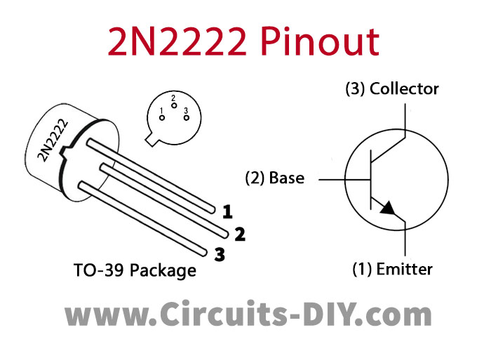
For a detailed description of pinout, dimension features, and specifications download the datasheet of 2N2222
IR Receiver Circuit
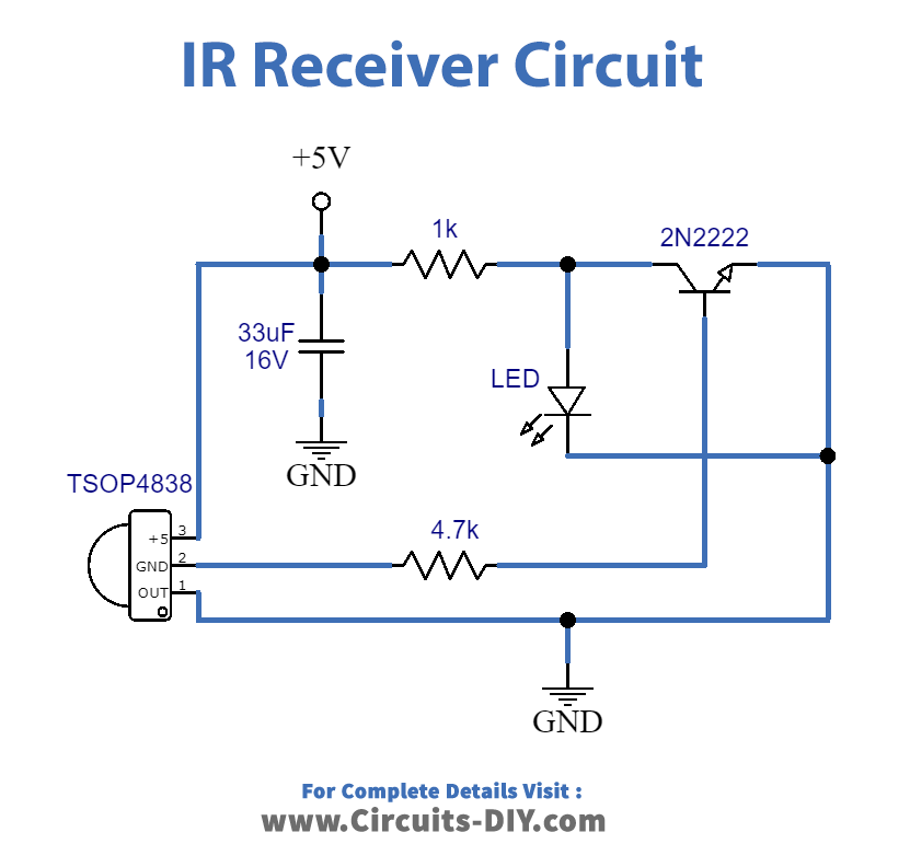
Working Explanation
The working of the circuit is simple. An IR receiver, when receiving the light of 38kHz, it transmits an electrical signal to the transistor. The transistor 2N2222, hence, amplifies the base signal and sends it to the light of the LED. Therefore, the blinking of the LED is such that when 38kHz light is sensed, the circuit operates. Moreover, a combination of electrolytic capacitor and resistor filters any distorted electrical signal in the circuit.
Application
Has the ability to distinguish data signal from noise in the environment due to the difference in frequencies.