An FM transmitter circuit is a low-power radio transmitter that allows any device (such as an MP3 player or a smartphone) to broadcasts an audio signal stored in its memory to a standard car radio. Most of these transmitters plug into a device’s headphone jack and then broadcast the signal over an FM band frequency so that it can be picked up by any nearby portable radio. So, this circuit allows portable audio devices to make use of the louder or better sound quality of a home audio system or car stereo without requiring a wired connection. So, In this tutorial, we are going to build a simple FM Transmitter circuit using HEP720 Transistors.
An FM Transmitter is often used in cars. But, they may also be in fixed locations such as broadcasting from a sound card throughout a building.
Hardware Components
You will need the following parts to build this project.
| S.no | Component | Value | Qty |
|---|---|---|---|
| 1. | Breadboard | – | 1 |
| 2. | Connecting Wires | – | 1 |
| 3. | Battery | 9v | 1 |
| 4. | NPN Transistor | HEP720 | 2 |
| 5. | Condenser MIC | – | 1 |
| 6. | Enameled Copper Wires | – | 1 |
| 7. | Audio Jack | – | 1 |
| 8. | Trimmer Capacitor | 30pF | 1 |
| 9. | Electrolytic Capacitors | 20uF/3V, 5uF/12V, 0.05uF/3V, 0.01uF/10V | 1, 1, 1, 1 |
| 10. | Ceramic Capacitors | 47pF, 6.8pF | 1,1 |
| 11. | Resistor | 100K Ω, 47KΩ, 33KΩ, 3.3KΩ, 1.5KΩ, 470Ω | 1, 1, 1, 1 |
Circuit Diagram
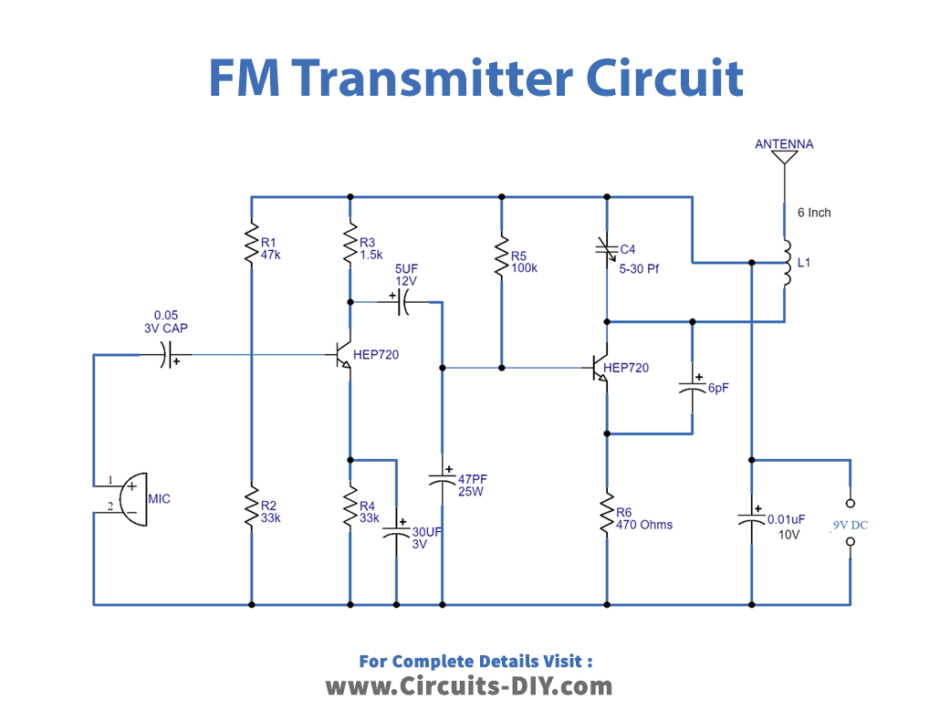
Working Explanation
This circuit is basically a combination of a microphone preamplifier & an FM transmitter.
So, the first stage of the circuit is a preamplifier stage based on transistor Q1. This is a collector-to-base biased amplifier stage where resistor R3 (1.5KΩ) sets the collector current and R1 (47KΩ) provides the necessary collector-to-base bias. C1 is the input DC decoupling capacitor which couples the input audio signal to the Q1 base. C7 is the power supply bypass capacitor.
In the second stage, this signal goes to the oscillator cum modulator circuit, build around transistor Q2 through the coupling capacitor. The coil and trimmer are in the parallel tank circuit. We specify the value of the trimmer and size of the coil such that the resonant frequency will be near 88-108 MHz (in the FM radio Band). The oscillator circuit generates a signal with a frequency determined by the value of the trimmer capacitor C5.
The output signal from the emitter of the transistor is coupled to the input of the transistor using the coupling capacitor. So, as this signal is amplified, the variable capacitor C5 in the Q2 transistor section tends to maintain an output matching that of the oscillator. The amplified signal is then transmitted using the antenna.
Applications
- A common part of old automobiles that do not support modern-day audio inputs such as auxiliary input (AUX) or Bluetooth connection.