Introduction
Introducing the ultimate solution to sleepy mornings! Tired of your bland alarm clock not doing the trick? Say goodbye to hitting snooze and hello to a jolt of wakefulness with our DIY screaming alarm circuit. Utilizing the versatile 555 timer IC, this circuit will start your day with a bang.
With just a few simple components, you can create an alarm that will be heard from miles away. Not only will this alarm get you out of bed, but it will also be the talk of the town. Impress your friends and family with your technical know-how, and always arrive on time for necessary meetings. Say farewell to snooze-button dependency and hello to a screaming wake-up call.
Hardware Required
You will require the following hardware for the Screaming Alarm Circuit.
| S.no | Component | Value | Qty |
|---|---|---|---|
| 1. | IC | NE555 Timer | 1 |
| 2. | Capacitor | – | 2 |
| 3. | Resistor | – | 1 |
| 4. | Resistor (LDR) | – | 1 |
| 5. | Speaker | – | 1 |
| 6. | Jumper Wire | – | 1 |
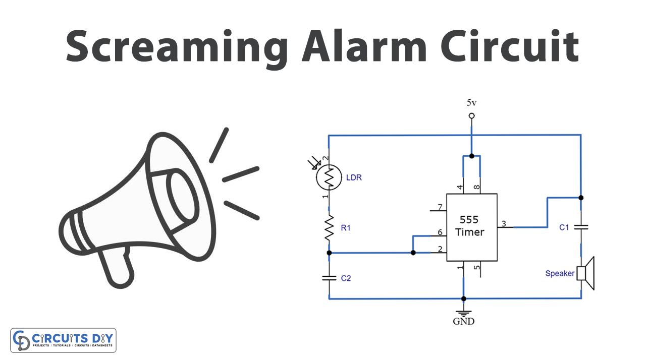
Circuit Diagram

Working Explanation
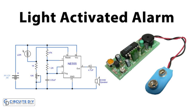
In this circuit, the IC 555 timer is the heart of the circuit because it helps the light-dependent resistors (LDR) oscillate based on how much light they receive.
555 Timer IC- A Heart of the Circuit
The IC 555 timer makes the oscillations that the system needs to work. As we know that we can use the timer in three different ways (Monostable, Astable, and Bistable), we used the Astable mode to avoid any triggers from the outside. In the circuit, the fourth pin is connected to the eighth pin on the 5V power supply. The speaker is wired to the third pin through the C1 capacitor.
In this case, following the astable pattern, Pin 2, connected to Pin 6, allows the circuit to be set off continuously. As soon as the 5V is sent to VCC, the LDR and R1 resistors start charging the C2 capacitor. When the capacitor reaches 2/3 of VCC, Pin 3 is triggered, and the rest of the charge is released through R1. This is how the pulse is made. Again, charging starts when the capacitor is 1/3 of the way to VCC.
LDR- A Crucial Part
Along with the timer, the light-dependent resistor is also an important part. In theory, a light-dependent resistor has a high resistance when there is no light. Once it starts getting light, the resistance goes down. Here, we also used 2 mega ohm photo resistors. The two LDR resistors and the 1K ohm resistor keep the serial connection. They are also linked to the 100nF capacitor C2. The two pins on the 6th and 2nd are joined together, and the C2 capacitor is connected to them. The ground connection is in the other part of the capacitor.
Speaker- Providing Output
The speaker is also a significant part of the circuit because it acts as a transducer to move the signal from an electric to a physical state. As the speaker has both fixed and moving magnets, they help turn the electrical signals into vibrations made by the IC555 timer. In this project, we used one 8-ohm speaker connected to Pin 3 of the 555 IC’s output through the electrolytic capacitor C1. Pin 3 of the IC is connected to the positive end of the capacitor’s terminal, and the negative end is connected to the positive node of the speaker and grounded.
So, screaming light is all about how intense the light is. The sound will get louder as the light gets brighter. Since the light sends an impulse into the circuit, it will make more sound when the light is brighter.
Final Words
In conclusion, the DIY screaming alarm circuit using the 555 timer IC is a fun and easy project for anyone looking for a more effective way to wake up in the morning. Give it a shot, and let us know if you have any questions!