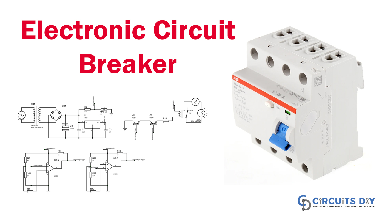
In this tutorial, we will show an electronic circuit breaker with high/low voltage protection. As far as we know, Harmonic distortion has become a challenge, and the majority of AC devices are responsible for the collapse. If it is a typical residential appliance like a toaster or a high-performance industrial machine like a CNC, it has only an applied power that operates at complete capability without problems. Regrettably, our household lines don’t supply us with rated voltage for multiple reasons, so we are building a simple electronic circuit breaker, which could activate a relay to smash the charges after detecting voltage.
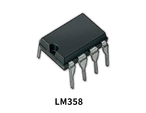
The renowned op-amp LM358 is designed for this construction process. We will do the op-amp work in variance mode so that the current voltage is particularly compared with a preset voltage. The construction process can be built on a panel (excluding power lines) and can be done immediately. Then let’s begin…
Hardware Component
The following components are required to make Electronic Circuit Breaker
| S.no | Component | Value | Qty |
|---|---|---|---|
| 1. | Dual Package Op-amp | LM358 | 1 |
| 2. | Diode Bridge | – | 1 |
| 3. | Capacitor | 0.1uF, 10uF, 100uF | 1, 1, 1 |
| 4. | Resistor | 1K, 2K, 2.2K, 5.1K, 10K | 1, 1, 1, 1, 1 |
| 5. | IC | 7805 | 1 |
| 6. | Transistor | BC547 | 2 |
| 7. | Step Down Transformer | 12V | 1 |
| 8. | Relay | 5V | 1 |
| 9. | Bread Board | – | 1 |
| 10. | Connecting Wires | – | – |
LM358 Pinout

For a detailed description of pinout, dimension features, and specifications download the datasheet of LM358
Electronic Circuit Breaker
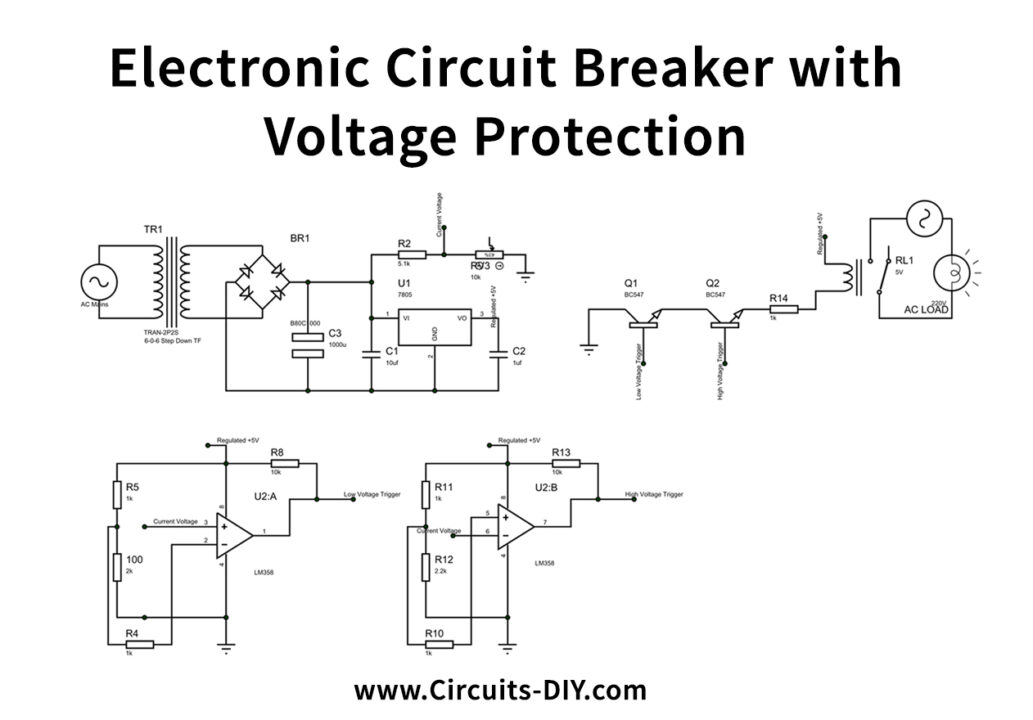
Circuit Operation
It’s just really simple and just many resistors, condensers, and other stuff, as shown above in circuit breaker schematics. But what happens behind all of these things? How and what is their role here when the values of the components are selected?
In breaking these into each segment and explaining them below, I tried to answer this question.
Power Section:
This electronic breaker schematic is central to the op-amp. To power this op-amp, we need a steady 5V supply. The current voltage (voltage) must be supplied to the op-amp at any particular time. The op-amp can only handle 5V because it has 5V power. Furthermore, the input AC voltage (220V AC) needs to be converted to 0-5V DC.
Thus the circuit above solves two objectives.
- Provide a 5V steady for the circuit power
- Maps the Voltage level for the op-amp up to 0-5V
For that intention, we have used a 12V transformer phase down that converts the 220V A-C to 12V AC. Afterward, we rectify the transmitter with a diode bridge to a 12V DC (Apx). Any alteration of the input voltage influences the voltage value of the diode bridge output side. That voltage also can be assumed as the AC mains’ “current-voltage.” We also plotted the voltage between 0-5V and used a 5.1k resistor and a 10K POT (forming a potential divider).
Op-Amp Section:
The compare section is placed in this section. In the op-amp segment, we have two sub-sections. One is used to update the actual voltage,” the other is used to contrast the low voltage value with the high voltage. The system displays both pieces.
The op-amp mentioned above circuit is an op-amp conditional mode. For most electronic circuits, Op-amp is just a working horse. It has multiple operating modes and applications such as summing, subtracting, amplifying, and so on.
Relay Section:
This is where the AC load is firmly attached. The relay is used to stimulate the AC load ON/OFF.
As specified in the section of the op-amp. Only if the voltage between high and low voltage cuts is the voltage between the two op-amps higher. Therefore, we must only trigger an AC load if the two outputs of the op-amp are strong. The output of pin 1 and pin 7, respectively, are the “Low Voltage trigger” and “High Voltage trigger.”
It will only take the relay to gain ground if they are both high, and they will be activated—the AC load id (a lamp here is related by the relay. For current limiting, a 1K resistor is used.
Applications and Uses
A circuit breaker is an electrical emergency brake that is automatically used to protect the electric circuit from overload or short-circuit damage caused by excess current. The essential feature of the Current Flowing Interrupt after a failure has been found.