Introduction
This guide will walk you through the process of building your very own Vibration Activated Alarm Circuit from scratch.
Building your own Vibration Activated Alarm Circuit is a fun and educational project and a great way to customize your alarm to fit your needs. With this circuit, you can choose the sensitivity level and the vibration sensor type and even add additional components, such as a speaker. Plus, once you’ve built it, you’ll have a one-of-a-kind alarm that you can use for all sorts of applications, such as securing a door or detecting movement in a room. So, whether you’re a beginner looking to learn more about electronics or a seasoned pro looking for a new project, the Vibration Activated Alarm Circuit is sure to be a fun and rewarding experience.
So, if you’re ready to take your alarm game to the next level, let’s get started!
Hardware Required
You will require the following hardware for Vibration Activated Alarm Circuit.
| S.no | Component | Value | Qty |
|---|---|---|---|
| 1. | IC | 4011B | 4 |
| 2. | Non Polar Capacitor | 100n, 1u, 4n7 | 3, 1, 1 |
| 3. | Polar Capacitor | 10u,100u, 2u2 | 1, 1, 1 |
| 4. | Variable Resistor | 47KΩ | 1 |
| 5. | Resistor | 68K, 1M, 220K, 4K4, 4Ω7 | 1, 2, 2, 1, 1 |
| 6. | Jumper Wire | – | 1 |
| 7. | Speaker | 8-16Ω | 1 |
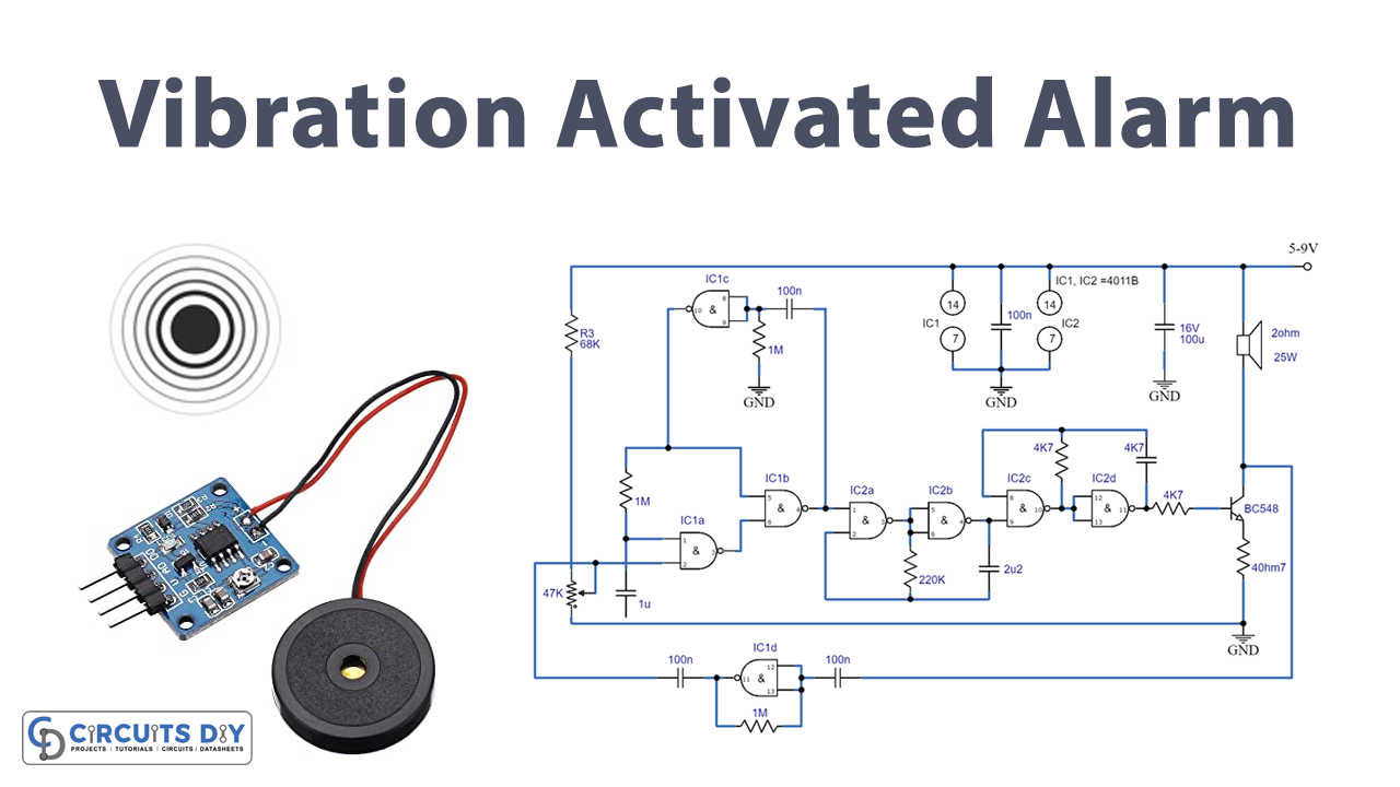
Circuit Diagram

Testing
To test the circuit that picks up a noise that surpasses an adjustable tolerance point, activating as a security alarm generator, follow these steps:
- Connect the circuit to a power source with a voltage between 5V and 9V.
- Adjust the trimmer R2 to set the threshold.
- Test the circuit by making a noise that surpasses the tolerance point and observe if the circuit gets activated.
- If the circuit is not responding to noise, check all connections and components for proper placement and continuity.
- Test the circuit with different noise levels to ensure it is correctly detecting and responding to disturbances.
- The circuit can also be used to identify a physical object according to a noisy sound, such as clapping both hands or whizzing noisily, test this feature by making different noises and observe if the circuit can identify the objects.
- Check the circuit’s power consumption to ensure that it is operating efficiently.
- Repeat the above steps with different sensitivity settings to ensure that the circuit is fully functional and programmable.
Working Explanation
This circuit is designed to function as an alarm generator that responds to disturbances. It works by picking up noise that surpasses an adjustable tolerance point, at which point it gets activated. The circuit can also identify a physical object based on a specific noisy sound, such as clapping or whistling.
The gate at the end of the schematic diagram functions as a linear low-frequency amplifier, thanks to the negative feedback resistor R3. The circuit obtains its input signal from a loudspeaker that serves as a microphone when the transistor T1 is cut off. The amplified output signal then goes through a capacitor to a second IC 4011 gate, activating a monostable circuit established by the two gates before and after the CS and R5. The DC threshold level is applied to pin 2 of IC1 via R2, and this DC voltage is superimposed on the signal coming from the capacitor.
The monostable circuit is designed to prevent retriggering, thanks to the collaboration of R4, C4, and the first gate. The sound generator IC1d stops the loudspeaker from functioning as a microphone once triggered. A high output signal through pin 4 of the monostable circuit enables a pair of astable multivibrators in IC2.
The first is a low-frequency generator that modulates the audio frequency tone generated by the second multivibrator. This creates a “siren” type of shrill sound that is heard from the loudspeaker. The transistor T1 is then powered via R8 to drive the loudspeaker hard. R9 slightly restricts the loudspeaker current. The length of the alarm signal is determined by the monostable time constant of R5 and C5. A low logic on pin 4 of IC1 blocks the sound generator. Once the time delay established by R4 and C4 has ended, the loudspeaker can again function as a microphone. A 5V can power the circuit to a 9V battery.
Final Words
In conclusion, building a Vibration Activated Alarm Circuit can be a fun and rewarding experience. Anyone can create this circuit with little knowledge and the right tools. Always follow proper safety guidelines, double-check your connections, and troubleshoot any issues that may arise. And always be curious and keep learning. If you have any questions or concerns, please feel free to ask in the comments section, and we will be happy to assist you. Happy building