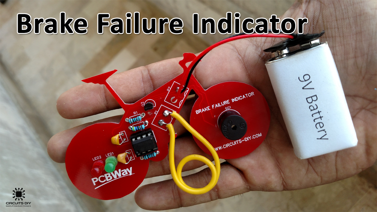
A Brake failure indicator circuit continuously monitors the braking system of any automobile such as a car, bike, or bus, etc. each & every time the vehicle is in operation. It is a mandatory part of any automobile vehicle. So, in this project, we are going to design a brake failure indicator circuit using a 555 precision timer IC.
The heart of this circuit is a NE555 Timer IC. The IC possesses an oscillation frequency ranging from 670 to 680 Hz. Here, this NE555 timer acts as an astable multivibrator An astable multivibrator is a free-running oscillator that switches continuously between its two unstable states. With no external signal applied, the transistors alternately switch from cutoff to saturation state at a frequency that RC time constants of the coupling circuit determine. If these time constants are equal (R and C are equal) then a square wave will generate with a frequency of 1/1.4 (RxC). Hence, an astable multivibrator is also a pulse generator or a square wave generator.
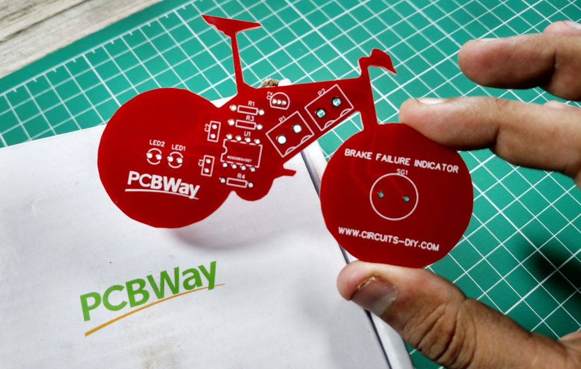
PCBWay commits to meeting the needs of its customers from different industries in terms of quality, delivery, cost-effectiveness, and any other demanding requests. As one of the most experienced PCB manufacturers in China. They pride themselves to be your best business partners as well as good friends in every aspect of your PCB needs.
Hardware Components
The following components are required to make Brake Failure Indicator Circuit
| S. No | Components | Value | Qty |
|---|---|---|---|
| 1. | IC | NE555 timer | 1 |
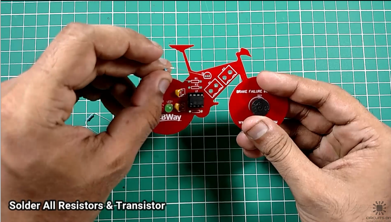
| 2. | PNP Transistor | 2N3906 | 1 |
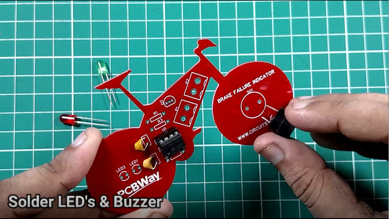
| 3. | Buzzer | – | 1 |
| 4. | LED | – | 2 |
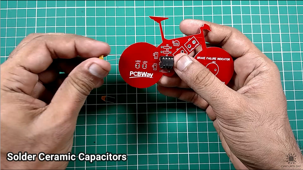
| 5. | Capacitor | 0.1µF, 1µF | 1,1 |
| 6. | Resistor | 440K, 1K | 1,2 |
| 7. | Battery | 9V | 1 |
| 8. | Breadboard | – | 1 |
| 9. | Connecting Wires | – | 1 |
NE555 Pinout

For a detailed description of pinout, dimension features, and specifications download the datasheet of NE555 Timer
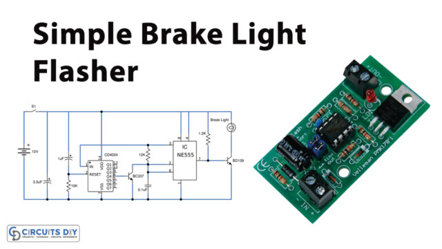
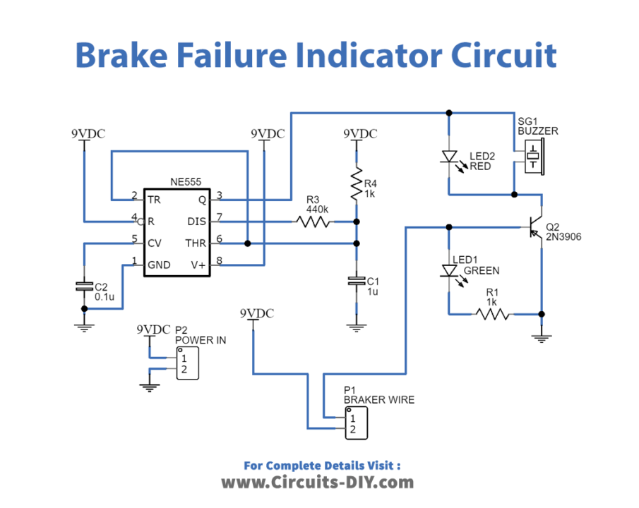
Brake Failure Indicator Circuit
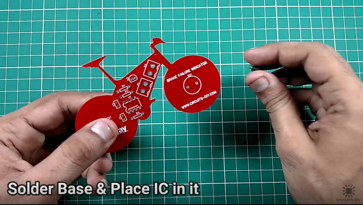
Steps

Working Explanation
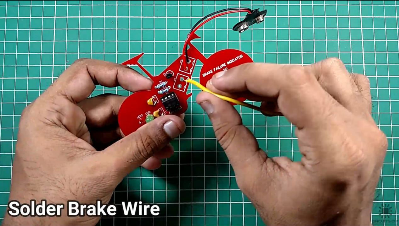
When turning ON the circuit, ensure that the Breaker wire is connected across the +9V DC supply and the base of Q2 (2N3906) through a resistor with respect to the circuit diagram in order to make sure properly working.
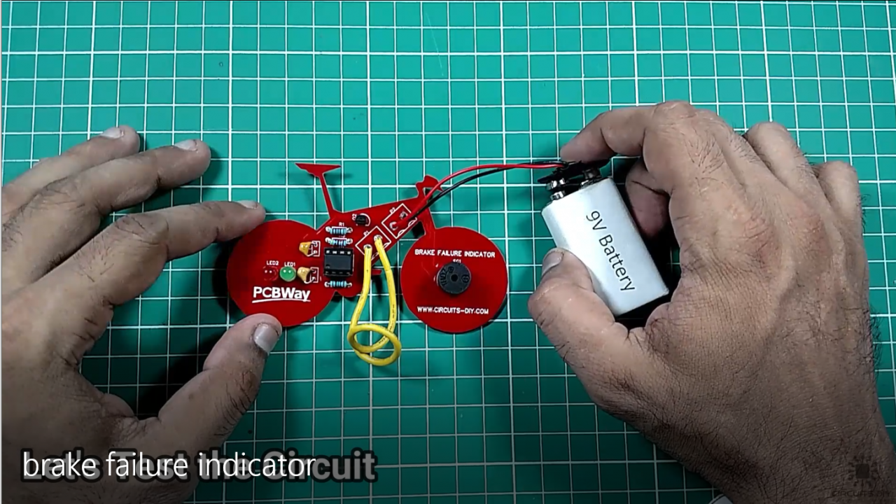
In standard operating conditions, you should see the Green LED turn on and the Buzzer and Red Light Turn Off. Now, removing or cutting the brake wire should trigger the Red LED and the Buzzer and they should start flashing/beeping, representing proper functioning.
Applications
- Usually serves as a fail-safe mechanism in vehicles such as Cars, Buses & Bikes.