Introduction
In your home, when you see the electrical sockets it always has the dimmer. But these dimmers are usually there to control the speed of an AC fan in your room, etc. However, it’s very uncertain that you have seen the dimmer to control AC lights. But, as the era and technology have evolved, now changing the light intensity of AC or DC lights is not a big deal. To consider that idea we are here with another project for beginners.
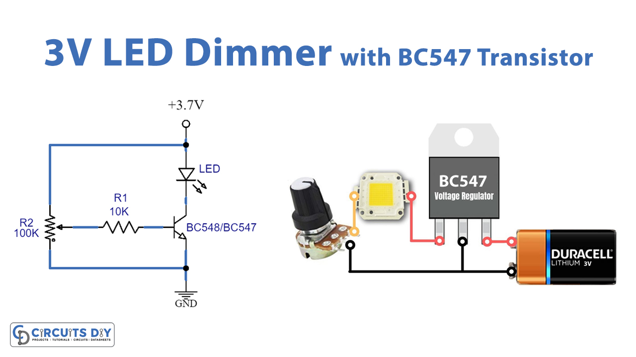
In this tutorial, we are going to Make a “3V LED Dimmer Circuit with BC547 Transistor”. Remember, this circuit can operate on very small DC voltage and can only control DC LED lights. BC547 transistor is usually used for amplification and quick switching.
Hardware Components
The following components are required to make 3V LED Dimmer Circuit
BC547 Pinout

For a detailed description of pinout, dimension features, and specifications download the datasheet of BC547
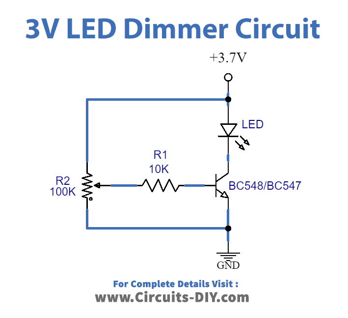
3V LED Dimmer Circuit
Working Explanation
In this 3V LED Dimmer Circuit with BC547 Transistor, the transistor is only connected with two major components, the potentiometer, and the output LED. Basically, the transistor has 3 pins. The potentiometer is wired with the base of the transistor therefore its rotation changes the base voltage. We can say that the intensity of the LED light depends on the rotation of the potentiometer as it creates different voltage levels for the transistor. In this way, the dimmer circuit works. The 10K resistor is necessary to be there for the protection of the transistor, otherwise, the transistor may be got damaged.
Application and Uses
- To change the light intensity of LED lights.
- DC lamps can use this circuit.
- With some modification, the circuit can use different loads to control different components.