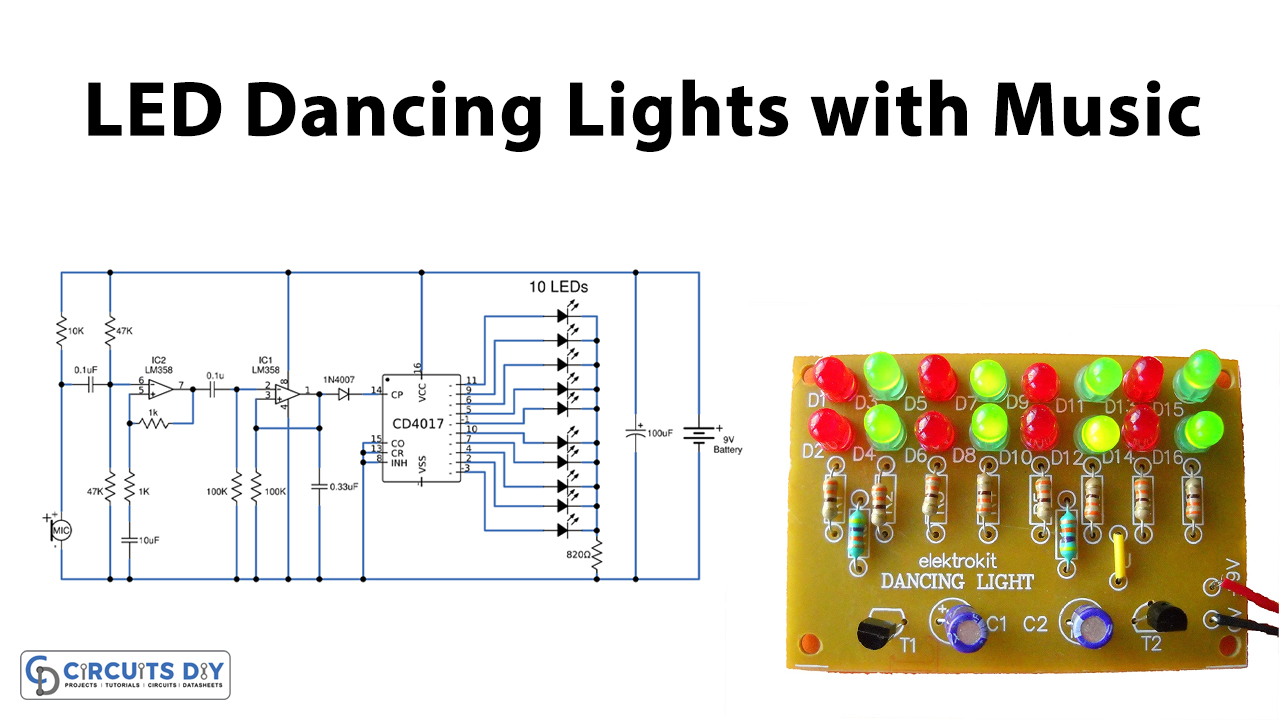
In this tutorial, we are going to make a “LED Dancing light circuit with Music”
LED Dancing light circuit is based on sound, glowing lights by changing the voice of the tiny microphone. You might have seen the Disco Lights or DJ lights or lights during a function that turns ON and OFF according to the beats or Rhythm of the music. These lights glow according to the length and pitch (volume) of music beats. These are designed to pick the high-intensity sound like Bass sound. The goal of this circuit is enjoyment and Sound experiment. It is very simple and easy to build, just requires a few basic components.
Hardware Components
The following components are required to make LED Dancing Light Circuit
| S.no | Component | Value | Qty |
|---|---|---|---|
| 1. | IC | LM358 | 1 |
| 2. | Decade counter IC | CD4017 | 1 |
| 3. | LED | – | 10 |
| 4. | Condenser Microphone | – | 1 |
| 5. | Resistor | 10K,47K,1K,100K,820 ohms | 1 |
| 6. | Ceramic Capacitor | 0.1uF, 0.33uF | 1 |
| 7. | Electrolytic Capacitor | 10uF, 100uF | 1 |
| 8. | Diode | 1N4148 | 1 |
| 9. | battery | 9V | 1 |
CD4017 Pinout
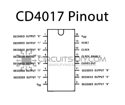
For a detailed description of pinout, dimension features, and specifications download the datasheet of CD4017
LED Dancing Light Circuit
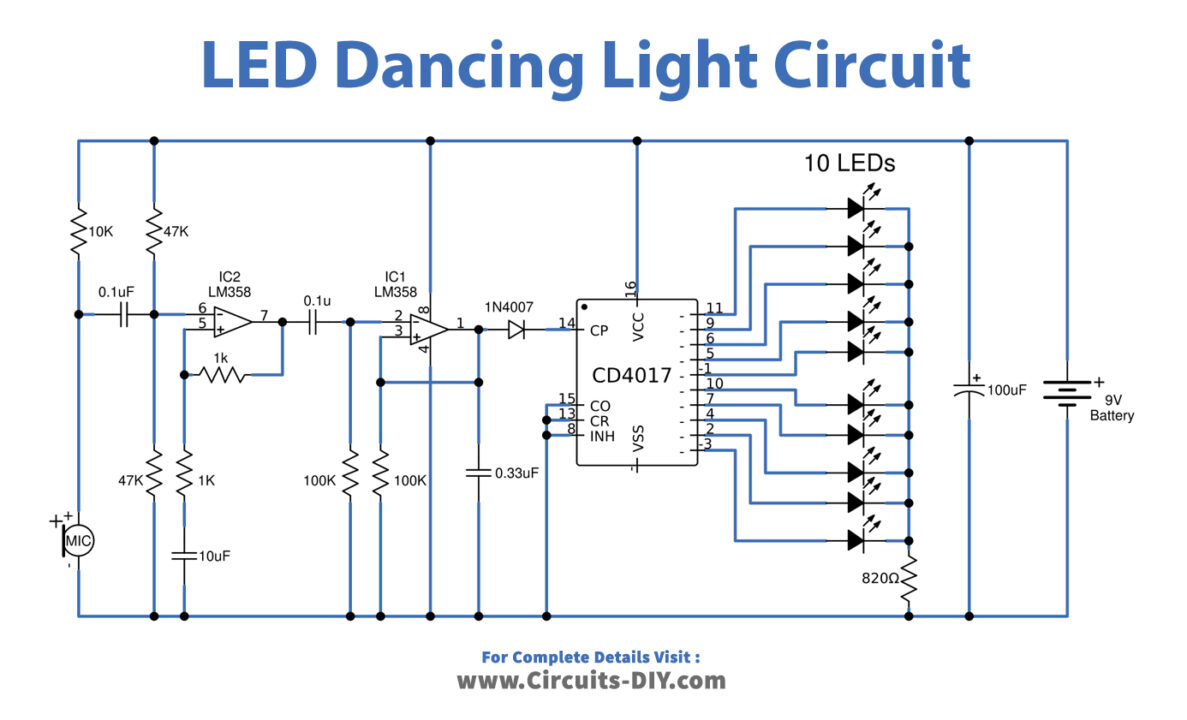
Working Explanations
As shown in the circuit diagram, when we connect the 9V battery to the circuit. R1 starts passing some current to MIC1 (Condenser Microphone), which transforms any sound signals into audio signals. C1 passes only an AC signal to the input and blocks DC.
Next, IC1/1(LM358), resistors (R2, R3, R4, R5,) and capacitor C2 are making the preamplifier circuit to increase the signal level high. And IC1/2 (LM358), resistors (R6, R7), diode D1, and capacitor C4 make a signal converter circuit. It will convert the electrical signal into a square waveform, to control the operation of pin14 of IC2.
The IC2(4017) is a popular decode counter circuit, that can drive 10 LEDs output. Its output pin will deliver voltage out in order sort of pin 3, 2, 4, 7, 10, 1, 5, 6, 9, and 11 in step by step. when IC2 gets a pulse input, it controls LED lights up following each step. It depends on the amount of an incoming square wave signal at pin 14. Resistor R8 limits the current of the LED for safety.
Applications
This circuit can be used in any function, event, or concert.