In this tutorial, we are going to make a “Cricket stump LED flasher circuit”. Innovation in cricket has traditionally been looked at with caution, especially by cricket’s more traditional fan base. And the introduction of bails with LED lights seems to have been almost universally accepted by fans, players, and administrators – a rare occurrence in modern cricket. Cricket had long struggled with stumping and run-out decisions, as it’s never been easy to determine the exact point at which a bail has been removed from the stump. The wide adoption of the decision review system, as well as the introduction of more camera angles. Further increased the need for determining the exact moment at which the bails were dislodged. The Australian company Zing International created the bails with LED lights.
The system is known as the Zing Cricket Wicket, or Zings for short. The lights in the bails help match officials make decisions in the game over the dismissal of batsmen. The lights flash only when both ends of the bail break contact with the stumps, which makes it extremely clear when the dismissal occurs. Since its approval by the International Cricket Council in 2013, the system has been used extensively in international matches and tournaments.
The bails would help address a problem that had plagued the sport for a while. Zings provided an easy and convenient solution. The bails would light up as soon as they were removed, which meant that every camera angle could be used to help make a decision. Here we design a simple and easy stump and bails LED flasher circuit. (Not for commercial use, zing has a patent). In this circuit, when the ball hit any one of the stumps, then LEDs in the bails & stumps will start flashing. The most widely used of all optoelectronic devices is the simple LED. Which emits a fairly narrow bandwidth of visible (usually red, orange, yellow, or green) or invisible (infrared) light, when its internal diode junction is stimulated by a forward electric current. LEDs have typical power-to-light energy conversion efficiencies some 10 to 100 times greater than a simple tungsten filament lamp and have very fast response times (less than 0.1µS, compared to 10s or 100s milliseconds for a tungsten lamp). Thus widely used as visual indicators and as simple ‘flashing light’ units.
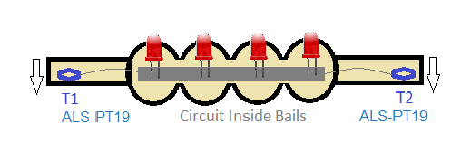
Position of Sensor in Bails
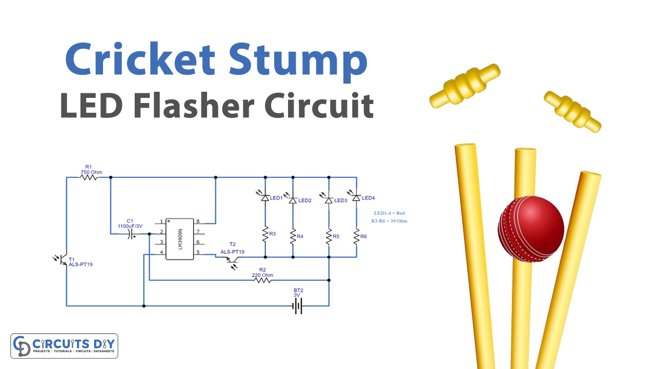
This circuit is designed by using IC1 LM3909, ALS-PT19 sensor, four red LEDs (5mm), and a few passive components. It can be easily constructed and placed inside the tiny bails without requiring more space. And you need a CR927 battery or you can use a tiny battery cell to make fit in your bails size.
Here the LED Flasher/Oscillator IC LM3909 is used to produce pulse output when the power supply is applied to pin 5 and pin 4. Two ambient light sensors (ALS-PT19) are placed on both corners of the bails, when the bails are placed on the stumps there is no possibility to sense the light. And the sensor acts as an open switch (T1 and T2), so the power supply cannot reach the flasher circuit. When the ball hits the stumps then the bails might float in the air so that sensors in the bails are gets exposed to the light. It acts as a closed switch (T1 and T2) due to this bias from the battery reaching the flasher circuit, so that the LED connected at the output glows alternatively.
Hardware Required
| S.no | Component | Value | Qty |
|---|---|---|---|
| 1. | IC | LM3909 | 1 |
| 2. | Transistor | ALS-PT19 | 2 |
| 3. | LED | – | 4 |
| 4. | Resistor | 750Ω,39Ω,220Ω | 1,4,1 |
| 5. | Capacitor | 1100uf/3V | 1 |
| 6. | Connecting Wires | – | – |
| 7. | Battery | 3V CR927 | 1 |
Circuit Diagram

LM3909 LED Flasher/Oscillator Pinout

Working Explanation
As shown in the circuit, each stump is placed with ALS-PT19 as a sensor and switch for the flasher/oscillator IC LM3909. Here on top of the stumps, two bails are placed to cover three stumps. Powered by hidden low voltage batteries, once the wicket is broken. The bails instantaneously flash bright red LED lights and send a radio signal to the stumps, which also light up. It reacts as an open switch and the LEDs are in an off state when the presence of the bails light sensor (ALS-PT19) couldn’t get any light. If the ball hits the stump then the bail might float in the air, since there are a lot of possibilities that the light sensor exposes to the light. So the light sensor reacts as a closed switch device, then this circuit gets the bias and produces a pulse at the output pin. Then the LEDs connected at the output glow alternatively.