Introduction
Sound intensity has crucial importance in various sound equipment and sound recordings. So, to understand the sound intensity or to, measure the audio level, volume unit (VU) meters are being utilized.
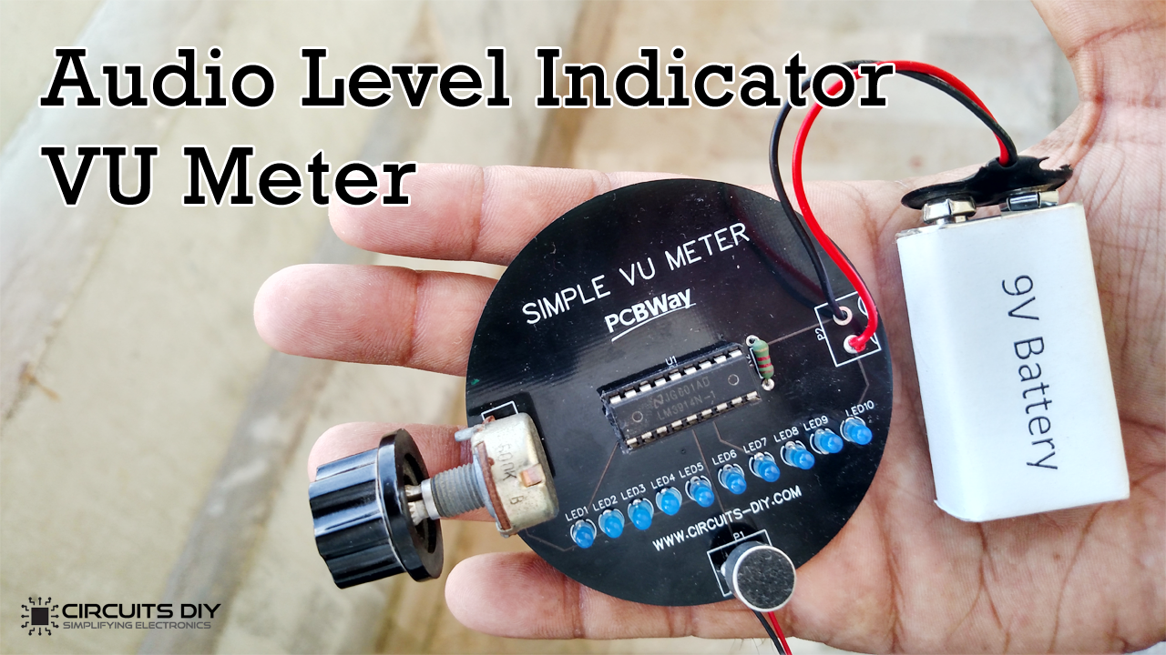
So, this tutorial is about making an Audio Level Indicator using LM3914 – VU Meter. This LM3914 is an LED-controlled derived IC that basically operates in two modes. A dot mode and a bar graph mode. Here, we will make a circuit in a bar graph mode.
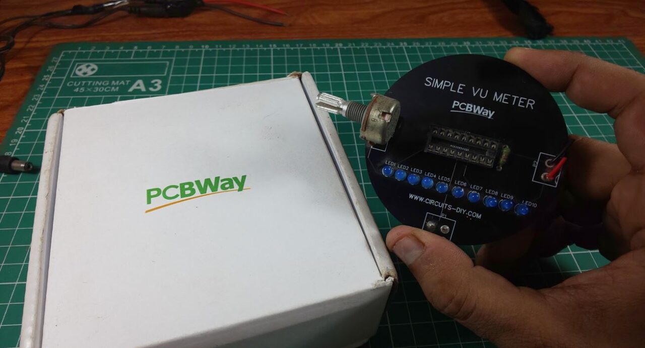
PCBWay commits to meeting the needs of its customers from different industries in terms of quality, delivery, cost-effectiveness, and any other demanding requests. As one of the most experienced PCB manufacturers in China. They pride themselves to be your best business partners as well as good friends in every aspect of your PCB needs.
Hardware Components
The following components are required to make Audio Level Indicator Circuit
| S.no | Component | Value | Qty |
|---|---|---|---|
| 1. | LED Driver IC | LM3914 | 1 |
| 2. | LED | – | 10 |
| 3. | Condensor Microphone/Smartphone | – | 1 |
| 4. | Audio jack port (Male) | 3.5mm | 1 |
| 5. | Potentiometer | 470K | 1 |
| 6. | Resistors | 1.2K | 1 |
| 7. | DC Power Supply | 12V | 1 |
| 8. | Connecting Wires | – | 1 |
LM3914 Pinout
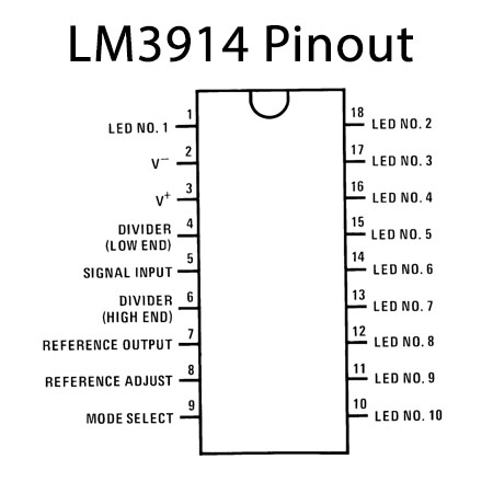
For a detailed description of pinout, dimension features, and specifications download the datasheet of LM3914
Audio Level Indicator Circuit

Working Explanation
In this Audio Level Indicator using LM3914, we provide the audio input at the signal input pin of an IC. The IC can work into different modes, the dot mode, and the bar graph mode. In DOT mode only one LED glows depending on the input and for this pin 9 remains open. On the other hand, in bar graph mode, LEDs turn on and OFF sequentially depending on the input voltage. And, for this purpose pin 9 needs to connect with pin 3. Since we want our circuit to work in bar graph mode. Therefore, we have wired pin 9 within 3 of an IC. Pin 7 is the reference out voltage, so here we have connected the resistor to set our reference voltage. Now, when you provide the audio signal to the circuit and the LEDs will glow according to the input of the audio signal.
Applications
- For music recording.
- To determine the signal level to avoid distortion and noise.
- To measure the sound intensity of various audio equipments.
- Tape recorders.
- Amplifiers.