Introduction
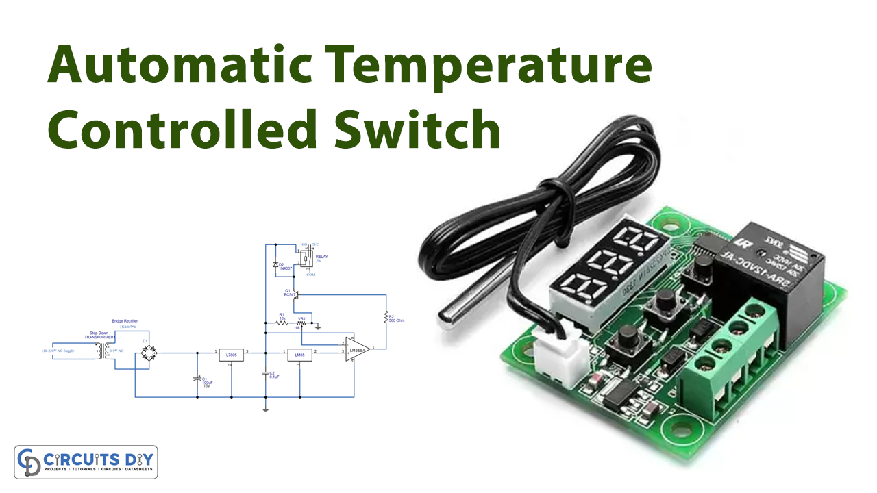
In this tutorial, we are going to make an “Automatic Temperature Controlled Switch”. It is designed to manage electric appliances by varying the temperature range that the user or operator must specify. This may be accomplished with the help of a temperature sensor. And, for this, we are using an LM35 temperature sensor.
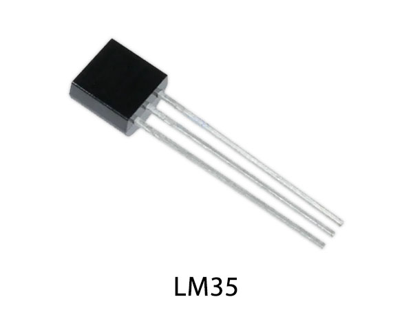
The LM35 is a temperature sensor with precession whose output voltage fluctuates depending on the temperature surrounding it. It’s a tiny, inexpensive IC that can monitor temperatures ranging from -55°C to 150°C.
Hardware Components
The following components are required to make Temperature Controlled Switch Circuit
| S.no | Component | Value | Qty |
|---|---|---|---|
| 1. | Step Down Transformer | 9v AC | 1 |
| 2. | Temp. Sensor | LM35 | 1,1,1 |
| 3. | IC | 7805 | 2 |
| 4. | Relay | 5v | 1 |
| 5. | Diode | 1N4007 | 1 |
| 6. | Potentiometer | 10K | 1 |
| 7. | Connector | 2-Pin | 1 |
| 8. | Transistor | BC547 | 1 |
| 9. | IC | LM358 | 1 |
| 10. | Capacitor | 0.1uf | 1 |
| 11. | Electrolytic Capacitor | 100uf | 1 |
| 12. | Resistor | 10KΩ, 560Ω | 1,1 |
LM35 Pinout

For a detailed description of pinout, dimension features, and specifications download the datasheet of LM35
LM358 Pinout

For a detailed description of pinout, dimension features, and specifications download the datasheet of LM358
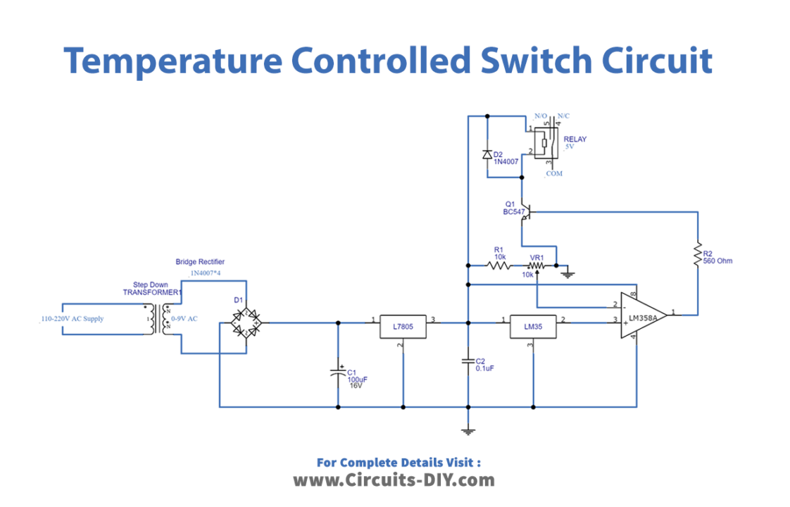
Temperature Controlled Switch Circuit
Working Explanation
Firstly, the Automatic Temperature Controlled Switch has a transformer that converts the 220V AC into 9V AC. Then, there is a bridge rectifier circuit, made up of four diodes that convert AC voltage into DC. Thus, the DC has ripples in it which are removed by the capacitor C1. Then, the IC 7805 regulates DC voltage and provides a consistent 5V DC supply. Now the output of this regulator IC is provided to the LM35 temperature sensor.
The LM358 operational amplifier assists us in selecting the temperature level with the help of the VR1 variable resistor, the output of which drives the Q1 transistor. When the output from the operational amplifier exceeds 2.5V, the Q1 transistor switches on and connects the relay coil to the Ground supply, causing the coil to activate and close the normally open contact.
Application and Uses
- The circuit can be utilized to control electrical appliances, and thus can be used for home automation systems.