Overview
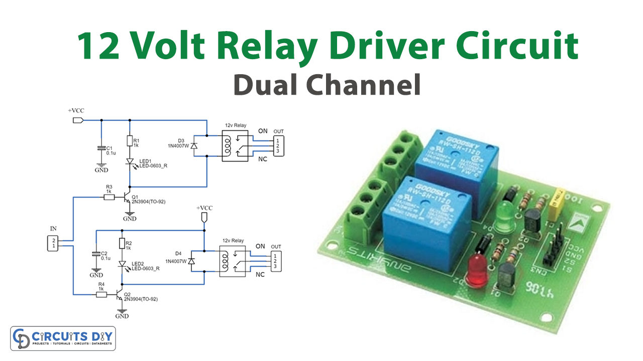
In today’s tutorial, we are going to make a “Dual Channel 12 Volt Relay Driver Circuit” using BC547 Transistors.
A simple and user-friendly method for interfacing two relays for switching applications in your project is provided by this relay driver. This driver enhances the input impedance using a standard BC547 NPN transistor (or an equivalent). It is a widely used driver capable of driving various types of relays, including reed relays. Transistors Q1 and Q2 function as a basic common-emitter amplifier, significantly boosting the sensitivity of the 12-volt relay coil by approximately 100 times. In simpler terms, the current gain for this circuit is 100, effectively reducing the relay sensitivity to just a few volts. To ensure safe operation, resistors R3 and R4 limit the input current to Q1 and Q2 within a safe range. Additionally, diodes D3 and D4 serve as electromagnetic field (EMF) dampers, filtering out any sparking that may occur when the relay is de-energized.
Hardware Components
To make Relay Driver Circuit, you’ll need the following hardware components to get started:
| S.no | Components | Value | Qty |
|---|---|---|---|
| 1 | Transistors | Q1-Q2 = BC547 | 2 |
| 2 | Capacitors | C1-C2 = 100nF-63V | 2 |
| 3 | Resistors | R1-R2 = 1K R3-R4 = 5.6K | 1 1 |
| 4 | Relay | L1-L2 = 12V | 2 |
| 5 | Diodes | D1-D2 = Red LED D3-D4 = 1N4001 | 2 2 |
Schematic

Specification:
- Input – 12 VDC @ 84 mA
- Output – two SPDT relay
- Relay specification – 5 A @ 230 VAC
- Trigger level-2~5VDC
- Berg pins for connecting power and trigger voltage
- LED on each channel indicates the relay status
Conclusion
This Dual Channel 12V Relay Driver Board Circuit offers a straightforward and efficient solution for interfacing two relays in switching applications. By utilizing a common-emitter amplifier setup with transistors Q1 and Q2, the circuit significantly enhances the sensitivity of the 12-volt relay coil, making it capable of driving various relay types including reed relays.